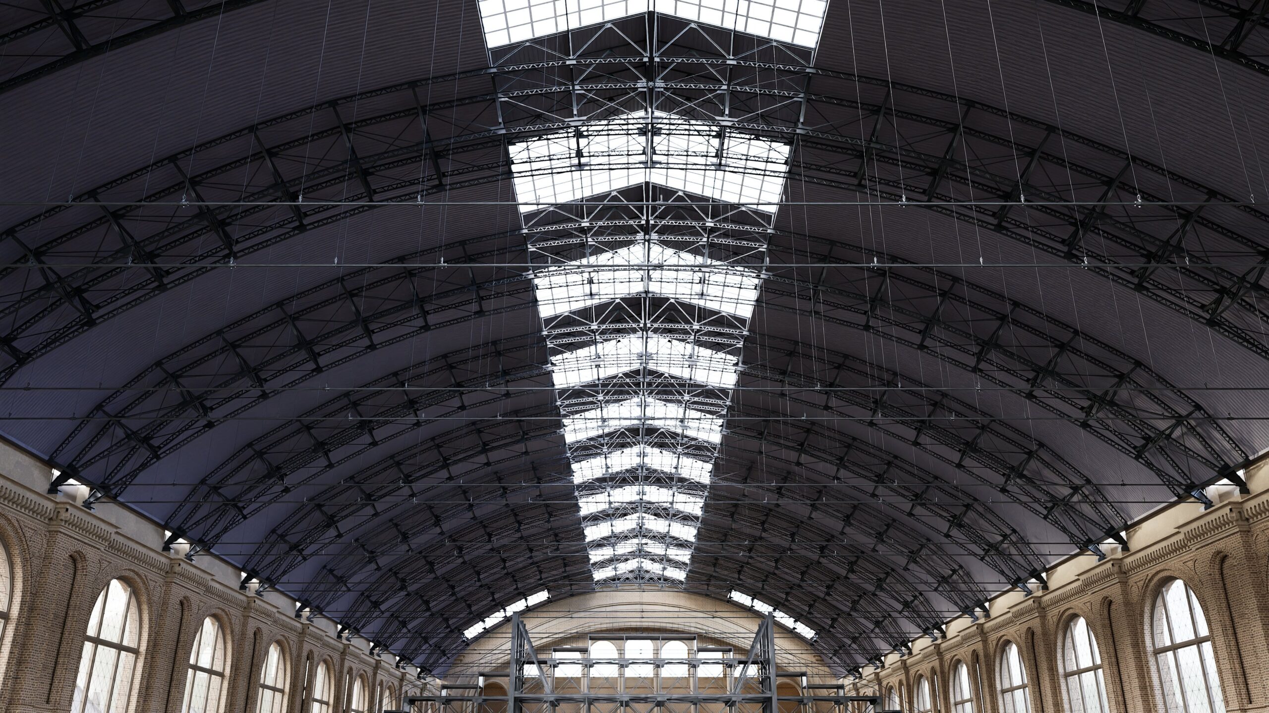
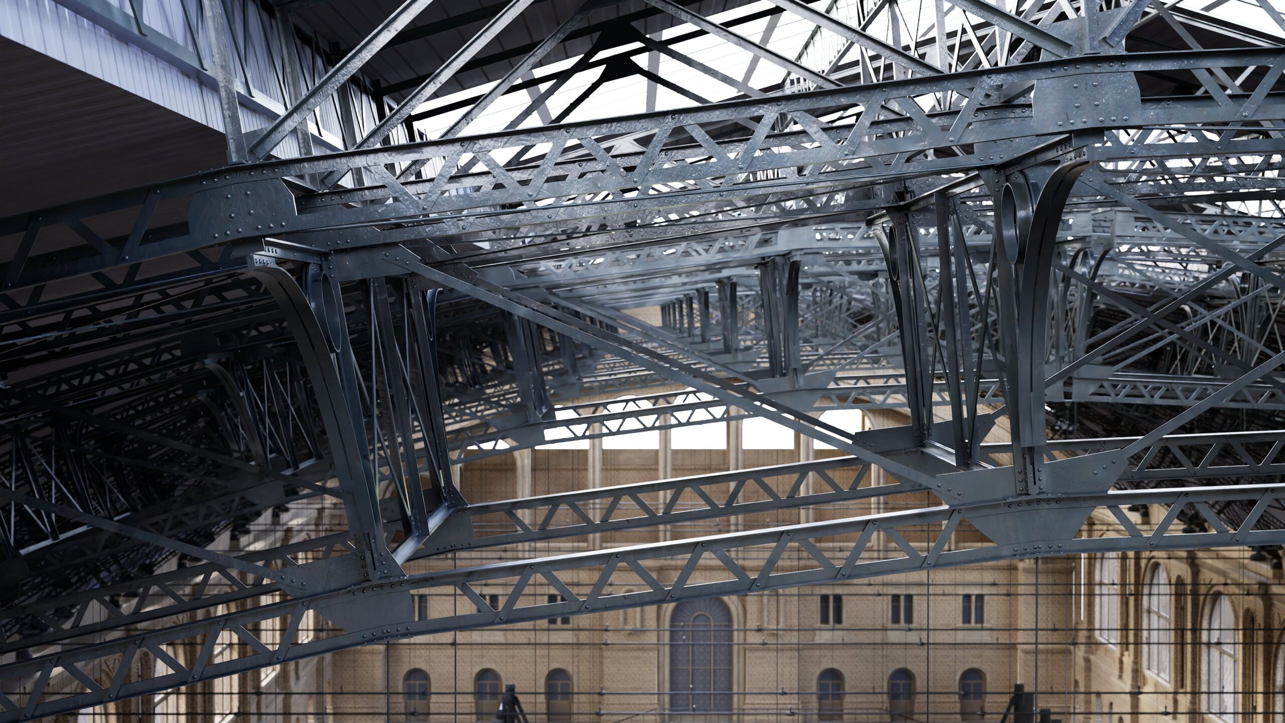
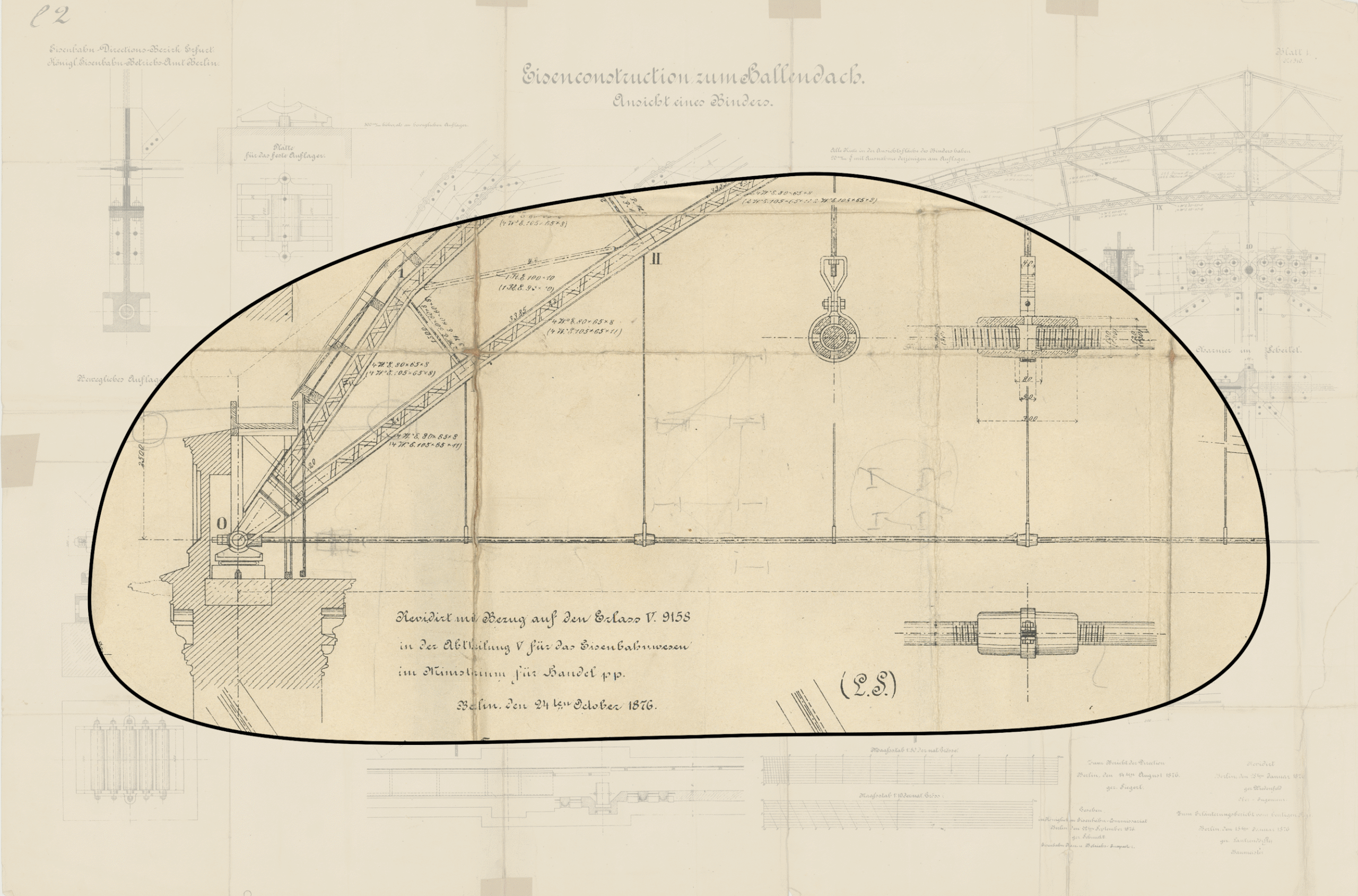
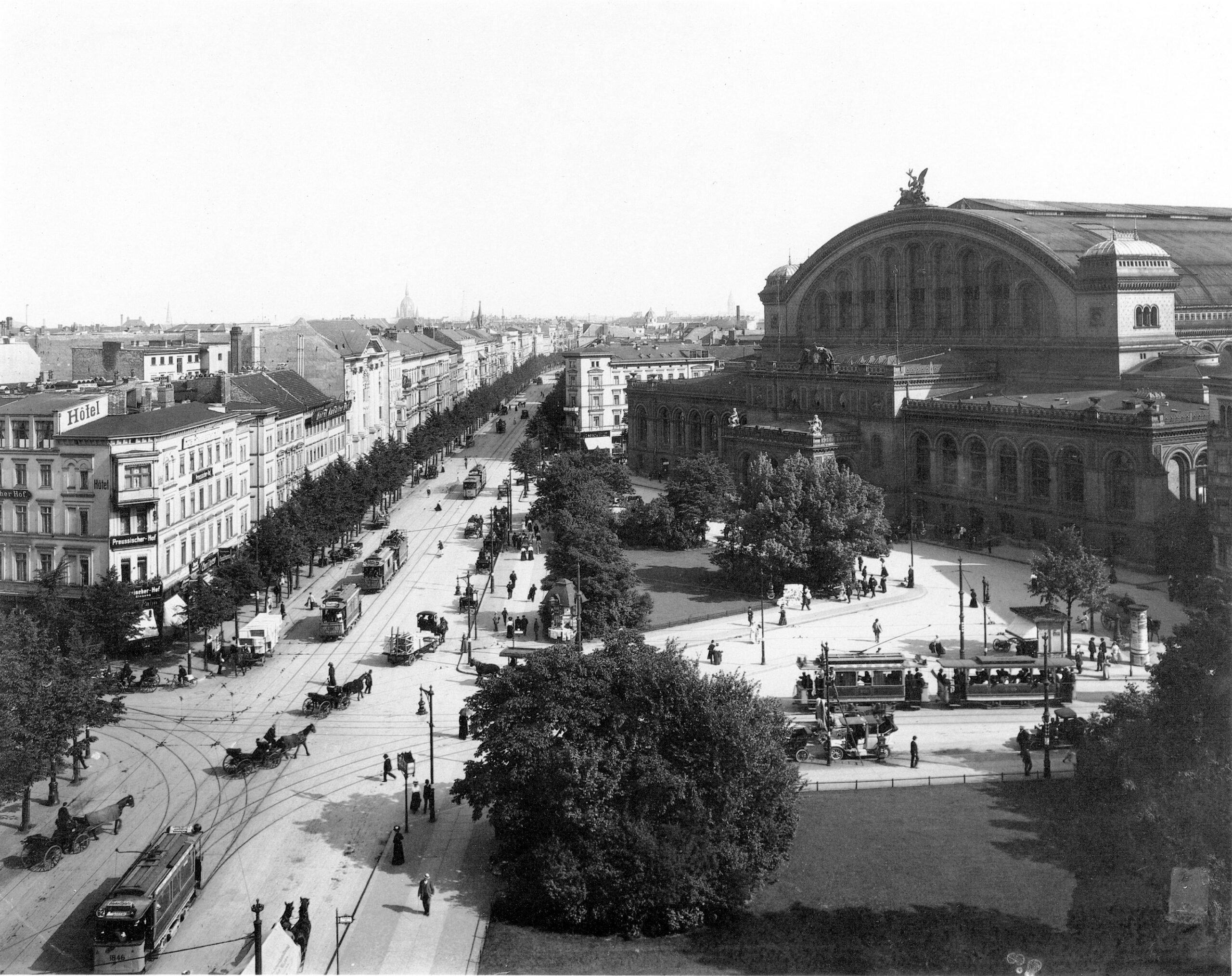
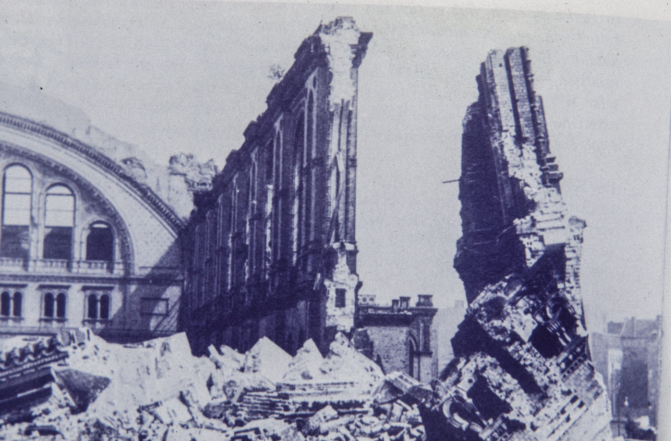
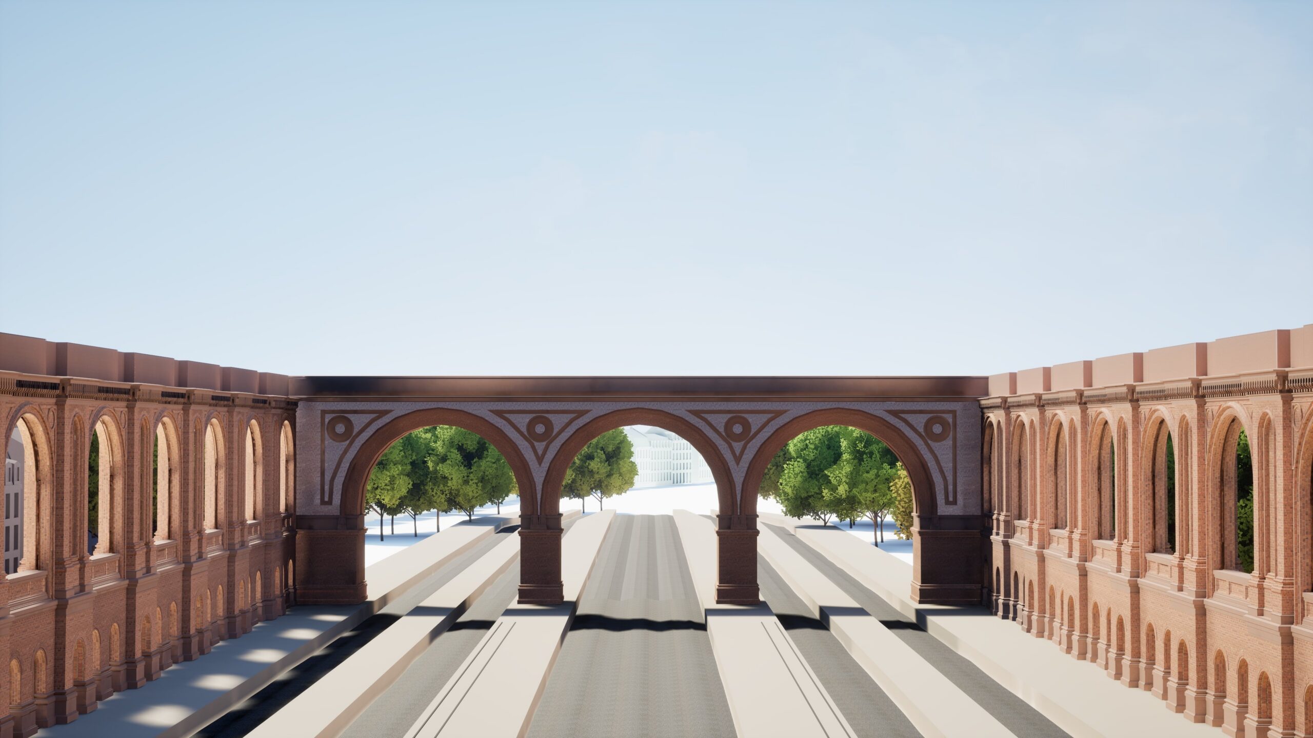
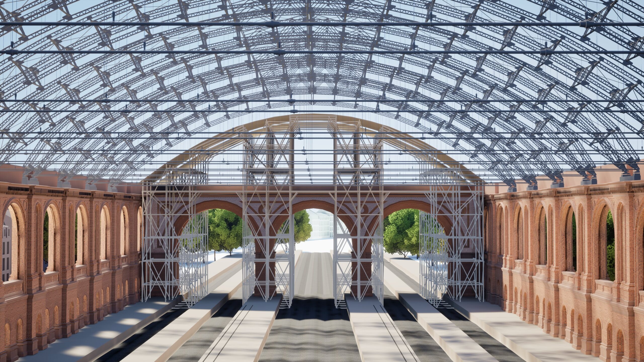
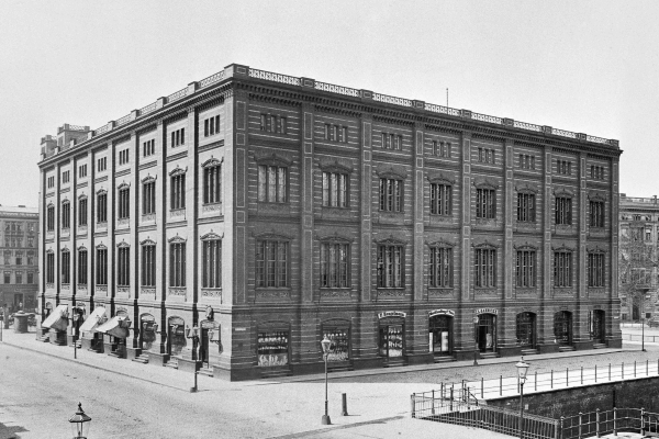
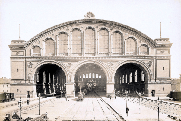
NEW STRUCTURE RECOVERED: The ANHALTER TRAIN STATION has been online since May 31. Enjoy exploring it!

The

“Anhalter”  
train station

The shell structures from the 1950s–90s are highly efficient, using double curvature to span large spaces with extremely thin concrete shells. Hand-calculated and economically built, they minimize materials, reduce CO₂, and are considered cutting-edge again today.

1875-1880

Five years of construction for Europe`s largest train station hall. Building materials arrived directly by train and had to be distributed only a few meters across the site. Today, five to five years is often barely enough to prepare for construction.

3000

One of the arch trusses consists of at least 3,000 individual steel parts and spans the then incredible 62.5 meters. The trusses were largely prefabricated, delivered to the construction site in a few individual parts, locally assembled and then moved to their final position using on site rail tracks.

70 mm

The iron arch trusses generate a considerable lateral thrust that the hall walls cannot absorb - they would simply tip over. For this reason, tie rods with a diameter of 70 mm were used to connect the two supports of the arches and take up the lateral thrust

February 1945

In February 1945, the impressive roof structure of the station concourse was severely damaged by Allied air raids during the Second World War and was dismantled in the late 1950s and early 1960s.

The shell structures from the 1950s–90s are highly efficient, using double curvature to span large spaces with extremely thin concrete shells. Hand-calculated and economically built, they minimize materials, reduce CO₂, and are considered cutting-edge again today.

The Anhalter Train Station

yr 1880 – 1960

  • Historical Background
  • History of use
  • Ownership History
  • Architectural Features
  • The “Anhalter” train station was built during the Industrial Revolution, the expansion of Prussia’s railway network, and Berlin’s political elevation to capital status. It embodies technological modernization, economic dynamism, and the ambition of national integration.
  • From 1880 until Second World War, the “Anhalter” train station was one of Berlin’s most important long-distance train stations, particularly for journeys to Southern Europe. During the Nazi era, more than 9,600 members of the Jewish community were deported from “Anhalter” train station to the Theresienstadt concentration camp. After suffering war-related destruction, the station remained in use until 1952, before being demolished in the early 1960s. Today, the preserved station portal serves as a reminder of the former station.
  • The ownership history of “Anhalter” train station reflects Germany’s changes: from 1875 it belongs to Prussia, from 1920 to the “Deutsche Reichsbahn”. After 1945, it is operated by the GDR-Reichsbahn in the Soviet sector. Following its closure in 1952, the site transfers to the state of Berlin.
  • The façade of the “Anhalter” train station, designed in the Neo-Renaissance style, was richly decorated and served as a representative symbol of the progress of the German Empire. Particularly impressive were the enormous, free-standing train hall and the sculptural group above the entrance featuring the sun god Helios, symbolizing light and speed.
1-4

Dive into the roof structure of the “Anhalter” Train Station

Click on the feature buttons and discover original drawings, photos, videos and explanations that tell you a story about the Art of Engineering.

The three hinged arch
The roof structure
The riveted truss girders
A Typical joint in the lower chord
The crown hinge
The support
The tie rod
The masonry structure
The roof construction execution

The three hinged arch

The roof structure

The riveted truss girders

A Typical joint in the lower chord

The crown hinge

The support

The tie rod

The masonry structure

The roof construction execution

The three hinged arch

The roof structure

The riveted truss girders

A Typical joint in the lower chord

The crown hinge

The support

The tie rod

The masonry structure

The roof construction execution

The three hinged arch

“Anhalter” train station in Berlin is one of the largest station buildings in Europe, featuring a remarkable roof structure composed of a total of 22 arched trusses. Although not visible in this image, these are three-hinged arches.
To explain the structural principle, we abstract the arch truss as a static system: a symmetrical three-hinged arch with two supports and a crown hinge.
At “Anhalter” train station, the hinge at the crown is not directly visible; Its design will be explained later.
A three-hinged arch has—as the name suggests—three hinges: two at the supports, also called springings, and as a rule one at the crown. This makes the system statically determinate, meaning that all forces occurring in the system can be determined using the equilibrium equations.
Vertical loads such as snow or dead weight act on the arch.. These primarily subject the arch to normal compressive forces and lead to reaction forces at the support - including horizontal forces!
The reaction forces must be securely absorbed at the supports, without any deformation occurring here. In particular, the supports must not shift due to the horizontal forces; otherwise, the arch will lose its structural function.
The magnitude of the horizontal forces depends only on the height of the arch. The flatter the arch, the greater the horizontal forces.
This is a particular challenge at the „Anhalter” train station. Here, the supports of an arch rest on the slender hall walls, which are over 23 meters high. The horizontal forces are so great that deformations may occur in the hall walls. The supports are pushed outward, causing the arch to lose its shape – and thus its effectiveness as a purely compression-loaded structural element. .
At the “Anhalter” train station, the problem is elegantly solved: a tie rod connects the springings, absorbing the horizontal forces and effectively closing the system.
The system is now force-locked and self-contained. The arch thrust pushes outwards, the tie rod pulls the arch back. This way, no horizontal forces from the arches are transmitted to the supports or the columns.
An arch with a tie rod no longer requires two fixed supports. For the “Anhalter” train station, a roller support was therefore chosen on one side, allowing small, unintended horizontal displacements. At the fixed support, however, small horizontal forces can occur, which is why the wall there was constructed 26 cm thicker.
At the „Anhalter“ train station, the crown hinge is not directly visible. Here, the hinge is located in the upper chord. The two parts of the arch are geometrically designed so that they only meet at the crown hinge. The lower chord is not continuous at the crown and does not serve a structural function there; it is only connected by a small plate to attach the suspension of the tie rod. The gap is only approx. 10 cm, barely visible, giving the impression of a continuous lower chord.
The theory of the three-hinged arch described here refers to geometry-related loads symmetrical load cases. The documents do not contain any information on how asymmetrical load cases were addressed during the roof’s design.
In the case of asymmetrical loads, bending moments also occur in the arch in addition to the axial compressive forces. These bending moments can be borne by the structural height of the trussed arch
1/7

The roof structure

The roof of the „Anhalter“ train station consists of 22 individual arched trusses with an impressive span of 62.50 meters. Two of the three-hinged arch trusses run parallel at a distance of only 3.50 meters and are connected to one another for spatial bracing, resulting in a total of eleven double arched truss systems.
This coupling provided stability during the sliding process.
In the historic floor plan, the eleven double arched truss systems are clearly visible.
Each system forms a load-bearing transverse axis of the roof structure and contributes to the bracing in the longitudinal direction of the hall. The double arched truss systems are distributed evenly along the hall’s length and have a spacing of 14.0 meters.
To illustrate the structure of the arched truss as well as of the double arch system , we examine section A-A across the hall, The roof structure will be described in detail below, based on this and additional sectional drawings.
The arched truss is parabolic in shape, designed as a three-hinged arch truss with upper and lower chords spaced 2.00 meters apart. A truss tie rod closes the arch at the lower section. The result: stability over a long span, an elegant form, and only vertical loads are transferred to the masonry below.
Each half of the arched truss consists of ten panels:
– 8 panels with parallel chords
– 1 trapezoidal panel
– 1 triangular end panel directly at the support.
This panel arrangement defines the load flow and the structural logic of the construction.
A double arched truss system consists of two of the previously shown arched trusses. The arched trusses are spaced 3.50 meters apart and are box-like connected by horizontal angle irons and diagonal flat irons. The upper braces extend 1.75 meters on both sides. These cantilevers reduce the clear span between two adjacent double arched truss systems.
Above the crown of the double arched truss system is a roof lantern constructed as a spatial truss structure.
It contributes to bracing in the longitudinal direction of the hall and enhances the structural stability of the roof framework.
Note: In the 3D model, you will find additional info buttons that allow you to take a closer look at individual details of the arched truss and to have the structural principle of the three-hinged arch explained.
1/7

The riveted truss girders

This excerpt from an original plan shows a section of the three-hinged arch truss.
Both, the upper and lower chords each consist of riveted small trusses that are 30 cm high.
These small trusses are composed of four angle irons and diagonals made of flat steel—a design that ensures strength while maintaining a slender construction.
1/7

A Typical joint in the lower chord

This excerpt from an original plan shows a typical joint in the lower chord of the three-hinged arch.
Here, the two small truss girders of the lower chord, a diagonal made of flat steel, a column composed of two angle irons, and the suspension of the tie rod all converge.
All component axes intersect at a single point—this prevents eccentric moments and ensures a clean load transfer. The connection is made using rivets.
1/7

The crown hinge

This excerpt from an original plan shows the crown hinge in the upper chord of the three-hinged arch.
The crown hinge is a central element of the three-hinged arch. It consists of a cast steel component and is connected to the right and left parts of the arch by bolts.
The two lower chords run parallel to the upper chord up to the axis of this hinge, but do not touch each other in accordance with the principle of the three-hinged-arch. They follow the formal geometry of the arch—without contacting each other in the middle.
The lower chords were likely extended at this point to achieve a desired arch shape. However, there is insufficient documentation to fully understand the exact background. From a structural perspective, is not required for a three-hinged arch.
1/7

The support

This excerpt from an original plan shows the roller support of the three-hinged arch on the wall pier.
At the support, the upper and lower chords meet. The forces occurring here are safely transferred into the support through a 40 mm thick gusset plate.
Numerous rivets and bolts ensure the load transfer. The roller bearing used at the western support allows horizontal movements—thereby preventing horizontal forces from being transferred into the masonry.
1/7

The tie rod

This excerpt from an original plan shows the tie rod of one of the three-hinged arch.
Since the hall walls cannot resist shear forces from the arch, the horizontal thrust is absorbed by iron tie rods.
These tie rods are anchored into the cast iron supports, equipped with tensioning threads, and suspended at the nodes of the lower chord using vertical tie rods to limit deflection.
1/7

The masonry structure

The roof of the hall of the „Anhalter” train station impressed with its span. Yet the masonry construction also represents an impressive structural system and will be examined more closely here.
The northern main façade with the entrance hall consists of multiple levels and an almost 40-meter-high gable wall—a delicate system of masonry round arches.
Massive columns, at least 2.35 meters thick, safely transfer the high loads from the roof structure into the ground.
The façade was intended to stand out from typical Berlin brick buildings. Therefore, the facing and backing masonry were constructed simultaneously—posing a special technical and aesthetic challenge.
This method offered both technical and aesthetic benefits: more precise dimensional accuracy, a more stable connection, and reduced wall thickness. It required well-coordinated planning and logistics.
The nearly intact masonry structure was completely demolished in the late 1950s and early 1960s. Today, only photographs and plans testify to its quality.
1/7

The roof construction execution

The construction method of the roof is just as fascinating as the structure itself. Building the largest roof in Europe required creative solutions to span the 62.5-meter-wide roof opening. The following section describes the assembly of the roof.
In earlier train stations, mobile scaffolding was used— with the disadvantage that other construction work in the hall was severely restricted. At the “Anhalter” train station, an alternative method was chosen: girder sliding instead of scaffolding shunting. The solide masonry crown of the longitudinal walls (approximately 1.50 meters wide) provided ideal conditions as a stable sliding track.
It is assumed that two fixed scaffolds were erected at the southern gable end of the hall—one in front of and one behind the still incomplete gable wall. On each scaffold, a double arched truss system consisting of two arched trusses was assembled. Both systems were then connected via the roof lantern. This coupling formed a system of two double arched truss systems, providing stability during the sliding process and preventing the structure from tipping.
Sliding of the truss systems
The fully assembled double truss systems were gradually slid northward and positioned along the respective column axes. In this way, the complete roof framework of the hall was constructed step by step—in five sliding operations, each time moving two systems simultaneously.
The final truss system
The eleventh and last truss system was assembled and slid into place individually—the exact circumstances remain historically unclear. With its placement, the complete load-bearing system of the hall was finalized and ready for the subsequent installation of the roof covering.
Open questions and documentation gaps
The exact location of the scaffolds is historically not definitively established:
– Were they erected inside, outside, or on both sides of the south façade?
– How was crane operation organized— in particular in the area of the scaffolding at the southern gable wall?
Such open questions highlight the limits of today’s reconstruction efforts but also provide valuable starting points for further research.
1/7

Explore the structure of the Anhalter Train Station in the comfort of your home.

Here you can download the entire VR exhibition of the Anhalter Train Station for free.

Pause

WHO MADE THIS PROJECT POSSIBLE?
WE GRATEFULLY THANK

Funding

Click here to access the complete image credits.

Where were the lost structures located? Find them on the map.

Berlin

The “Ahornblatt” Restaurant

This double-curved concrete shell structure enables large spans with minimal material use. Its futuristic form shapes the Berlin cityscape beyond the GDR era.

Berlin

The Berlin “Bauakademie”

This masonry skeleton construction is a prototype building with a uniform column grid, consisting of rib-reinforced vaulted ceilings, masonry columns , and arches, which set standards for economical and functional construction throughout Prussia.

Berlin

The “Anhalter” Train Station

This masonry structure with pin-jointed iron truss arches connects Berlin to the world. A train station whose innovative roof structure, at the time, featured the largest span in Europe.

Berlin

The Old “Kaisersteg”

This iron truss bridge with an arch and central hinge connects two districts of Berlin. With a main span of 86 meters, it was a technical masterpiece of its time and represents innovative bridge engineering of the late 19th century.

Schmehausen

The Cable Net Cooling Tower

The cable-net cooling tower of the Hamm-Uentrop nuclear power plant in Schmehausen is globally unique in its design. The load-bearing network of steel cables replaces traditional concrete structures, enabling an exceptionally lightweight and efficient construction.

Munich

The Munich Glass Palace

This cast steel and glass structure is built in 1854 using innovative industrial manufacturing processes in a very short time. Although intended as a temporary building, it shaped Munich’s reputation as a city of art for over 75 years through its exhibitions.

Weimar

The Hetzer Timber Halls

The timber halls of the company Otto Hetzer AG were based on a construction principle patented in 1906: glued and curved timber elements that enabled large spans – a groundbreaking innovation in timber construction.

Awareness information

Anhalter Bahnhof:

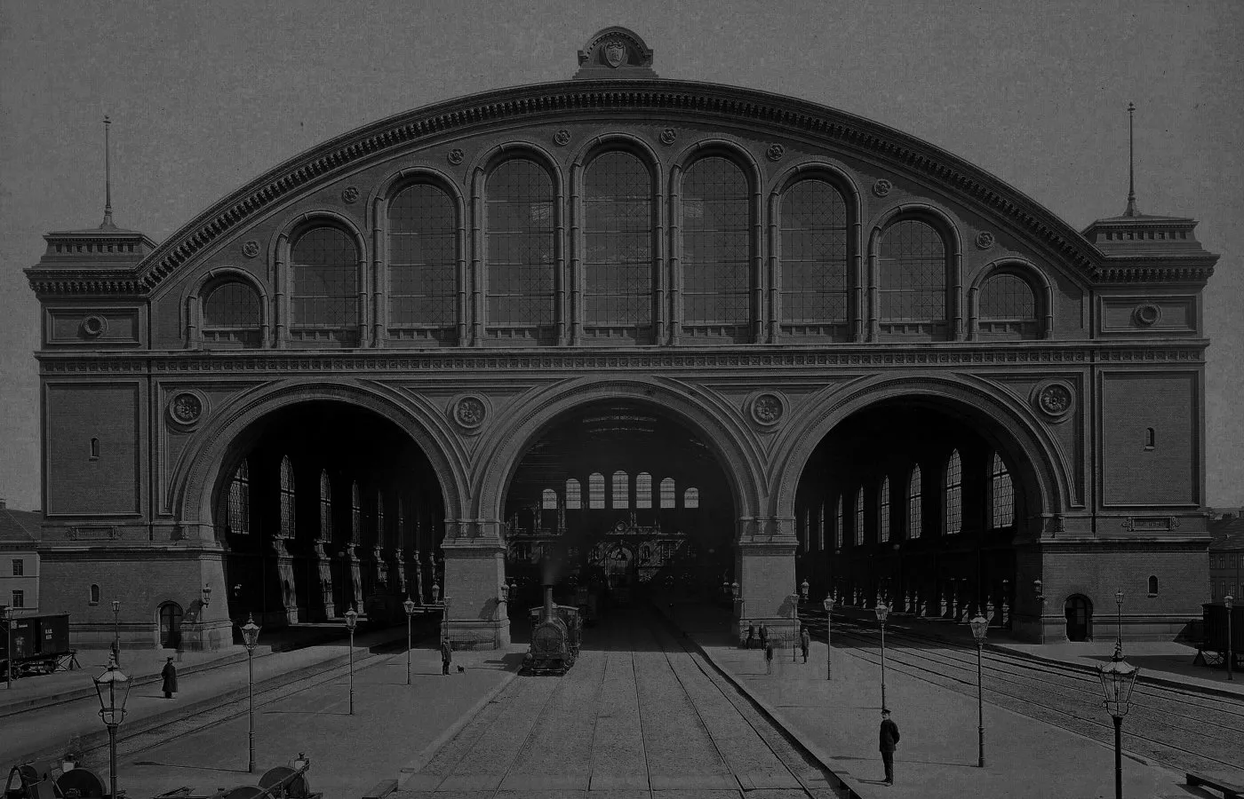
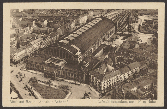
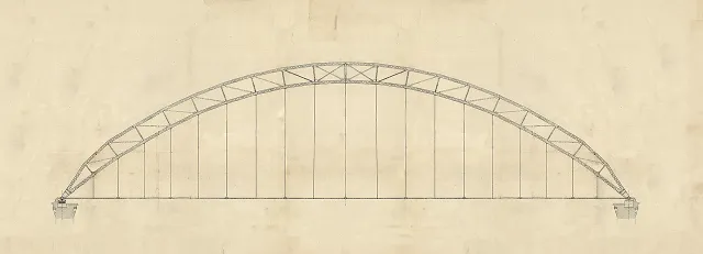
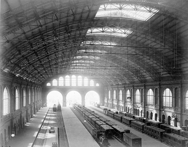
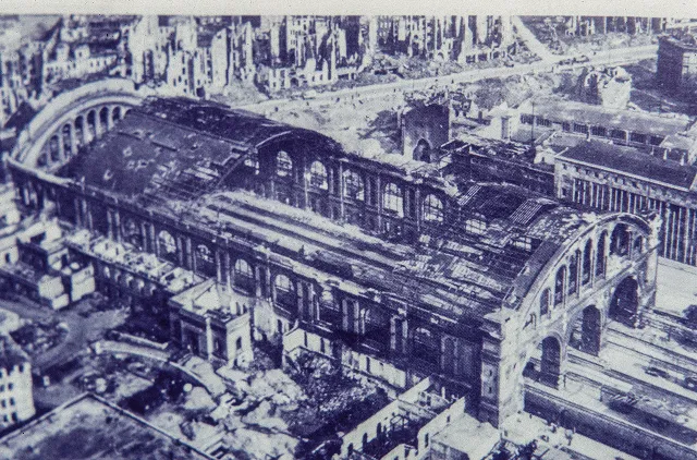
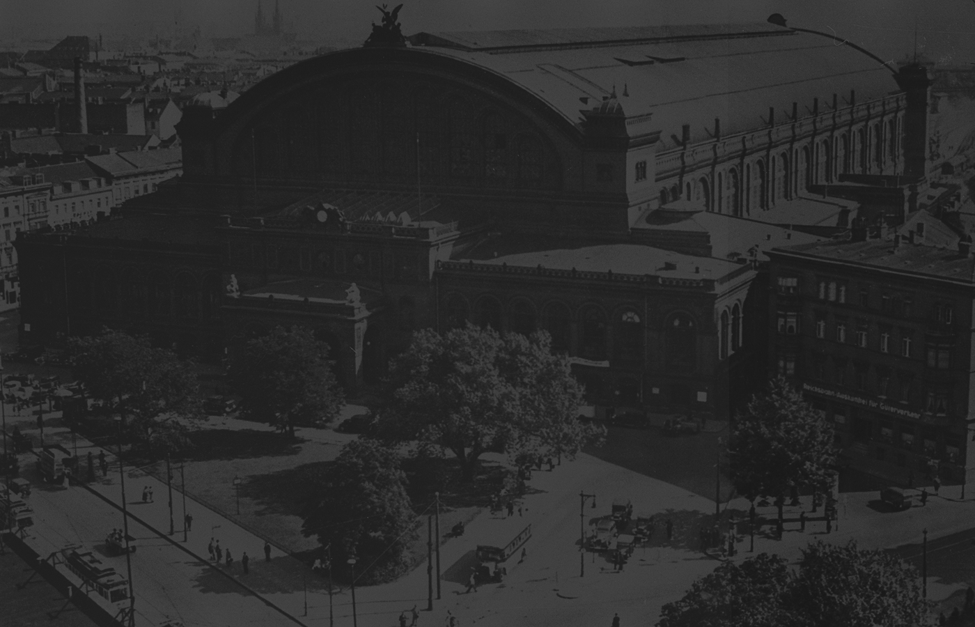
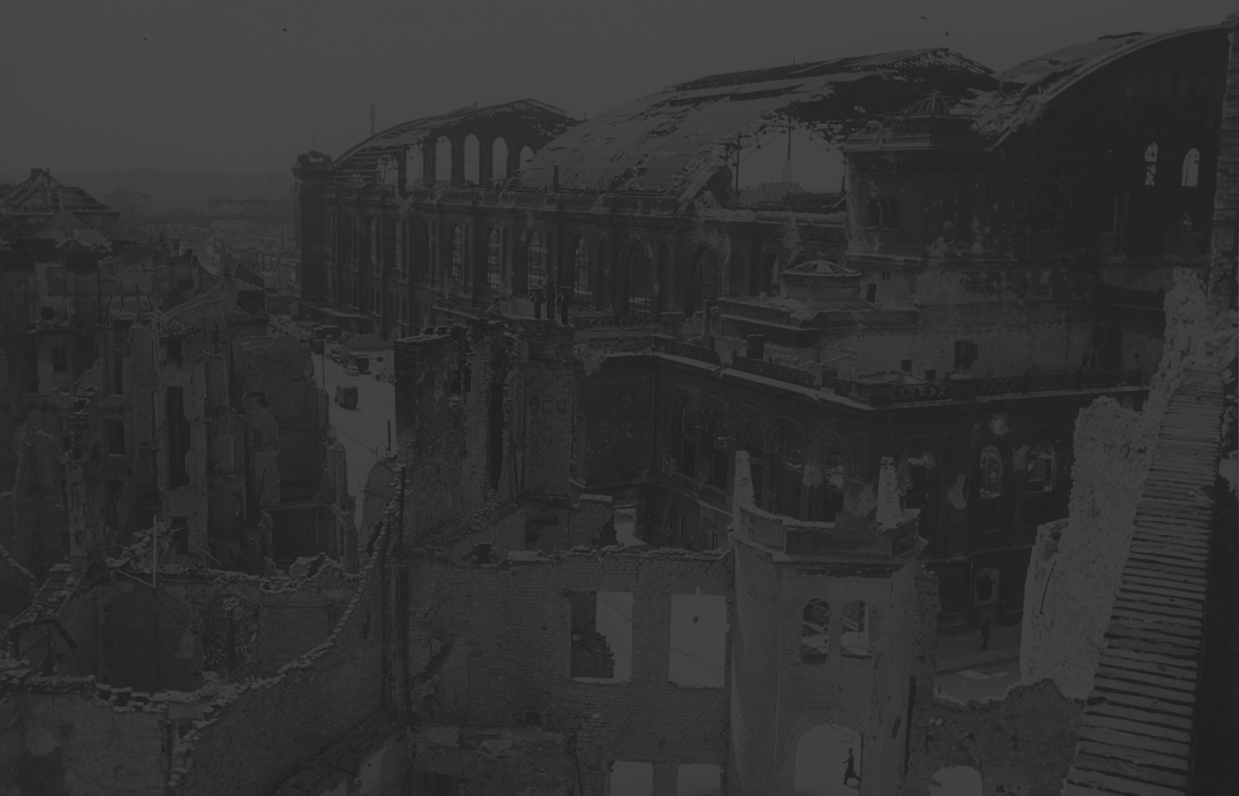
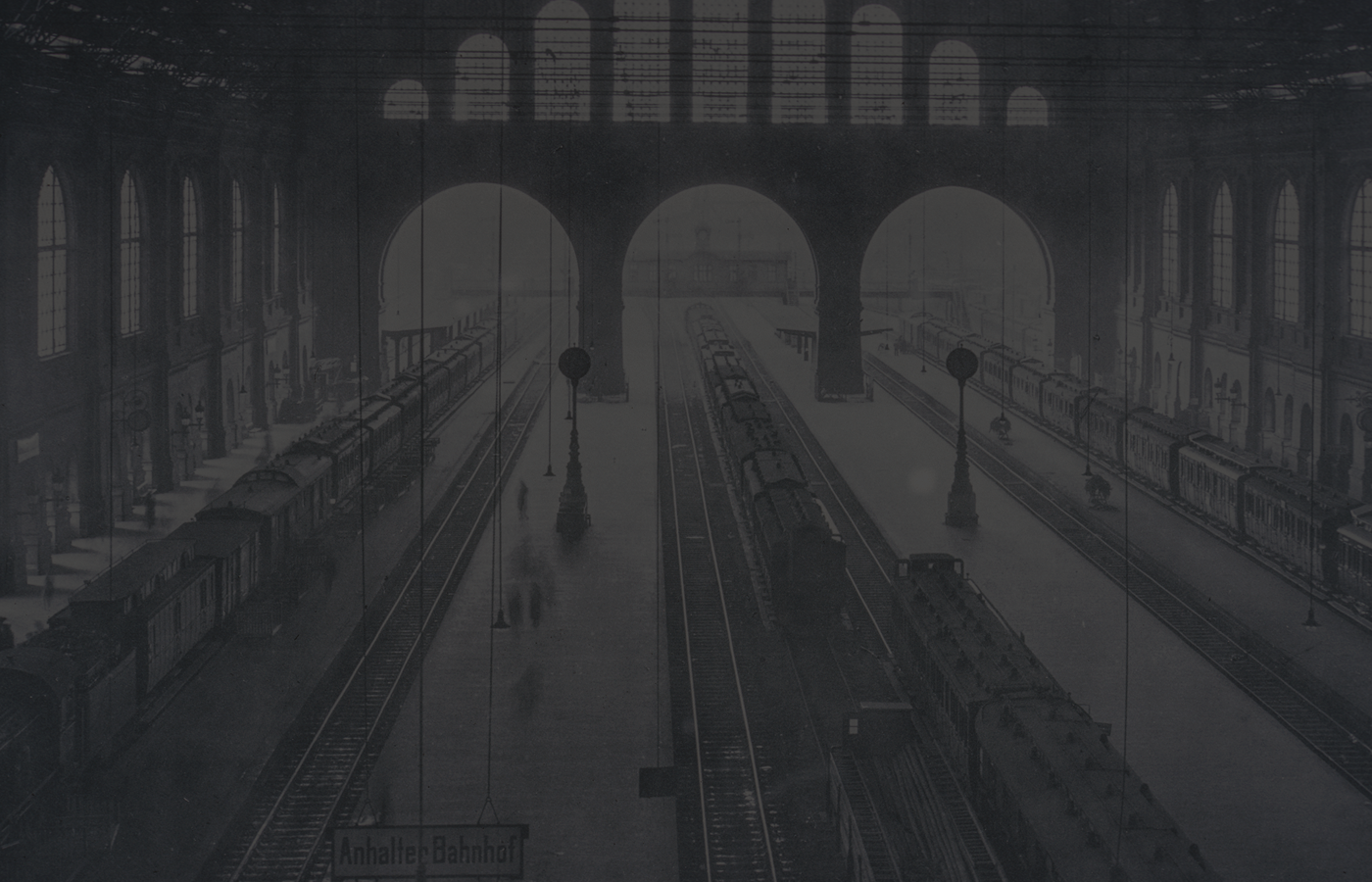
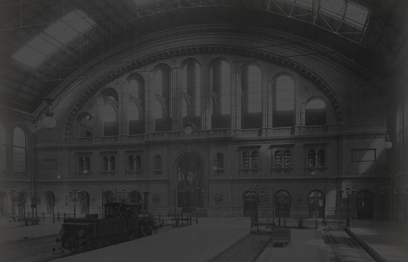
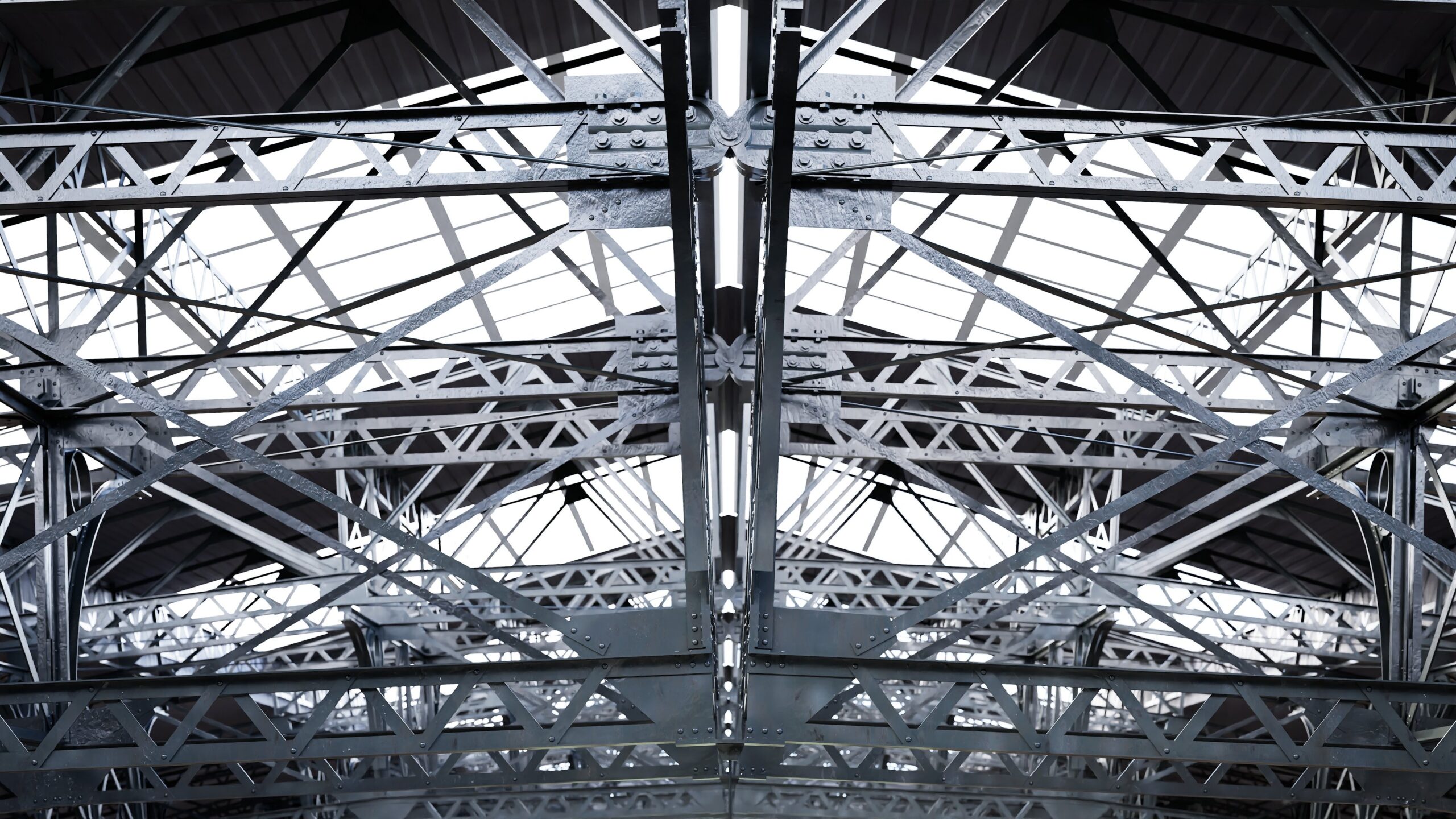
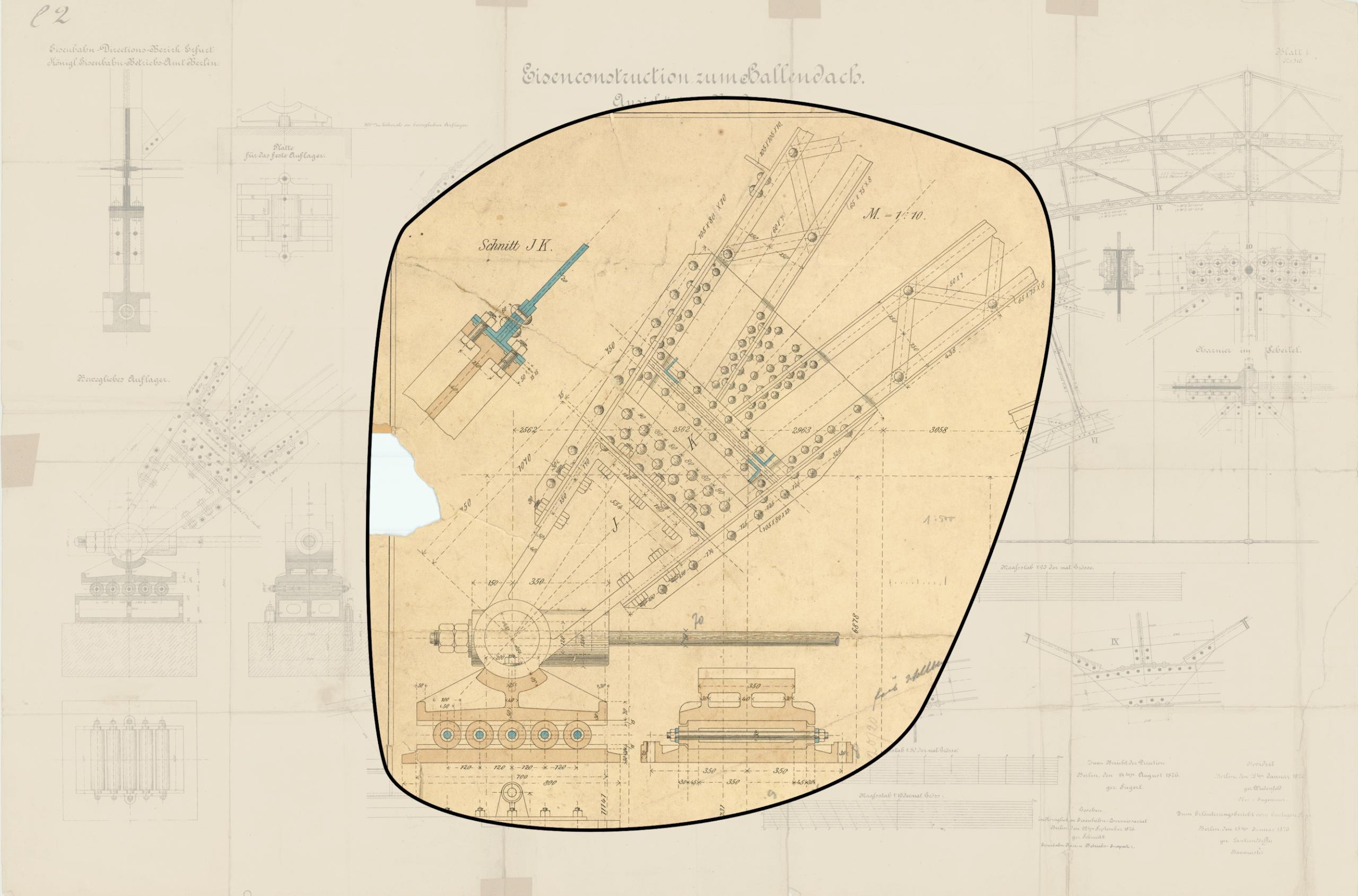
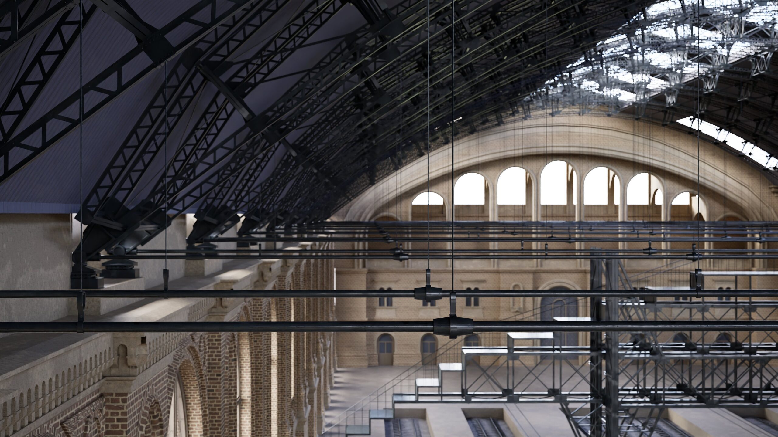
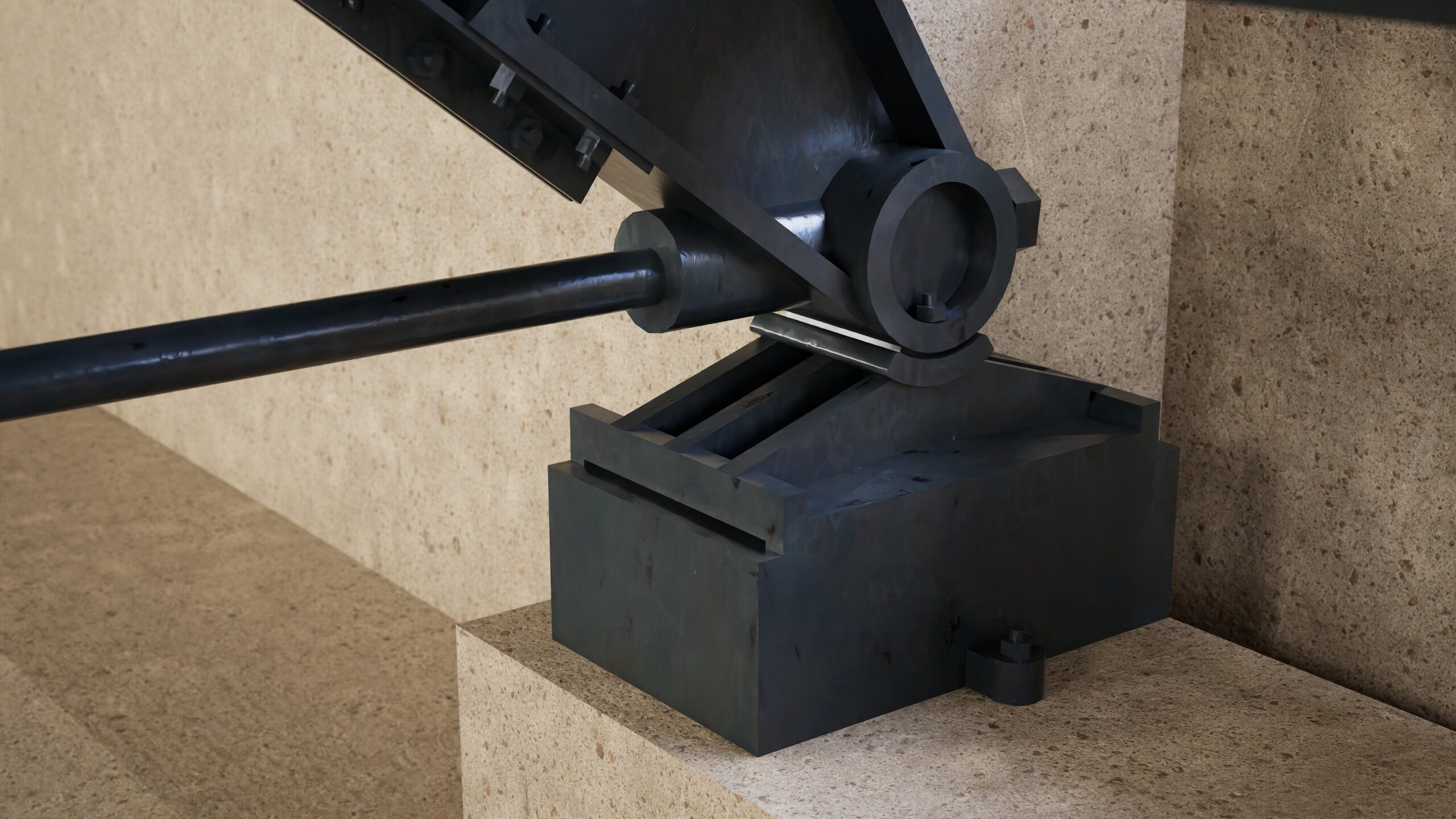
Large-scale structures like Berlin’s “Anhalter” train station tell stories not only of technical innovation and urban significance, but also of the often overlooked labor of those who built them.

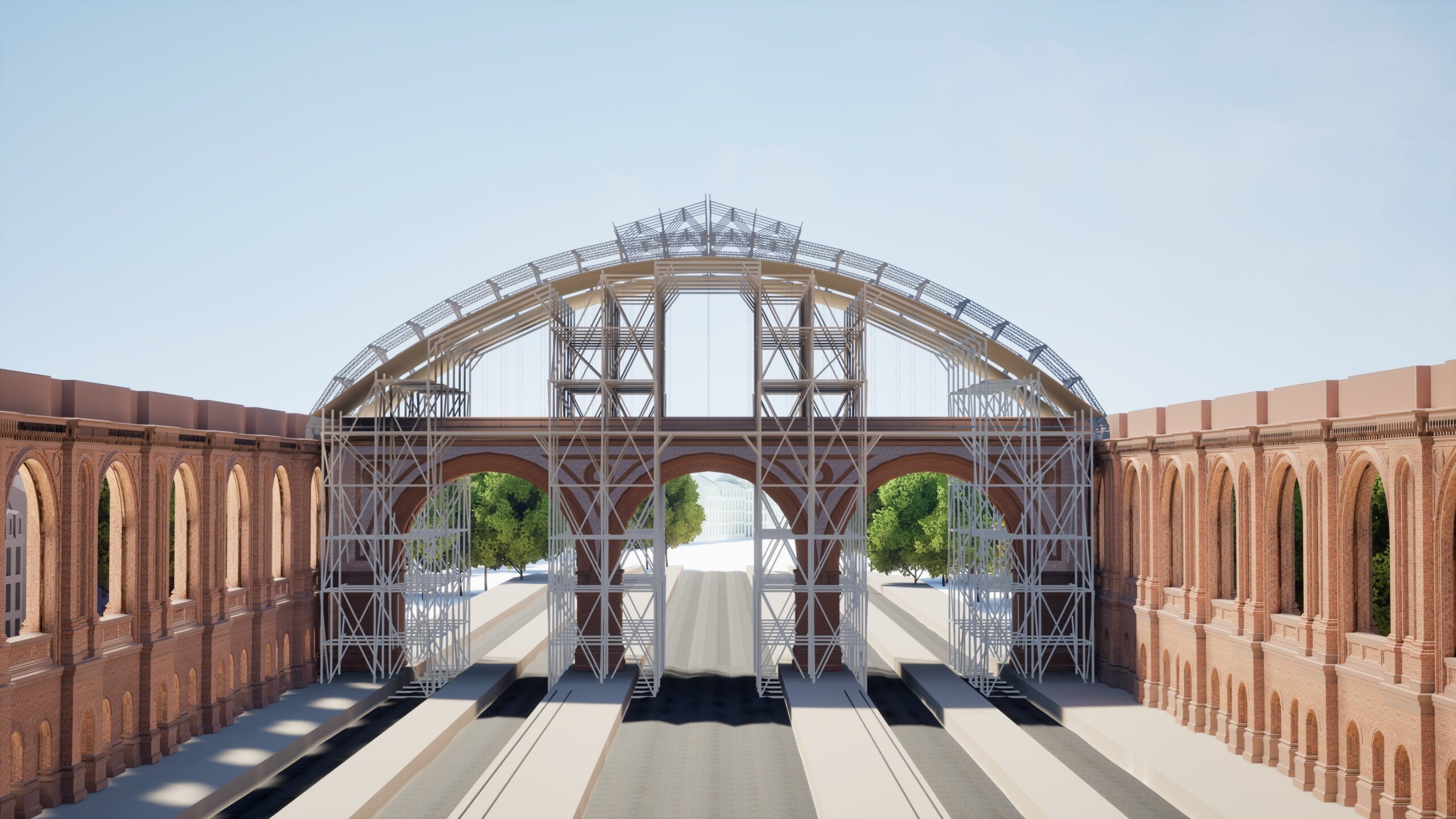
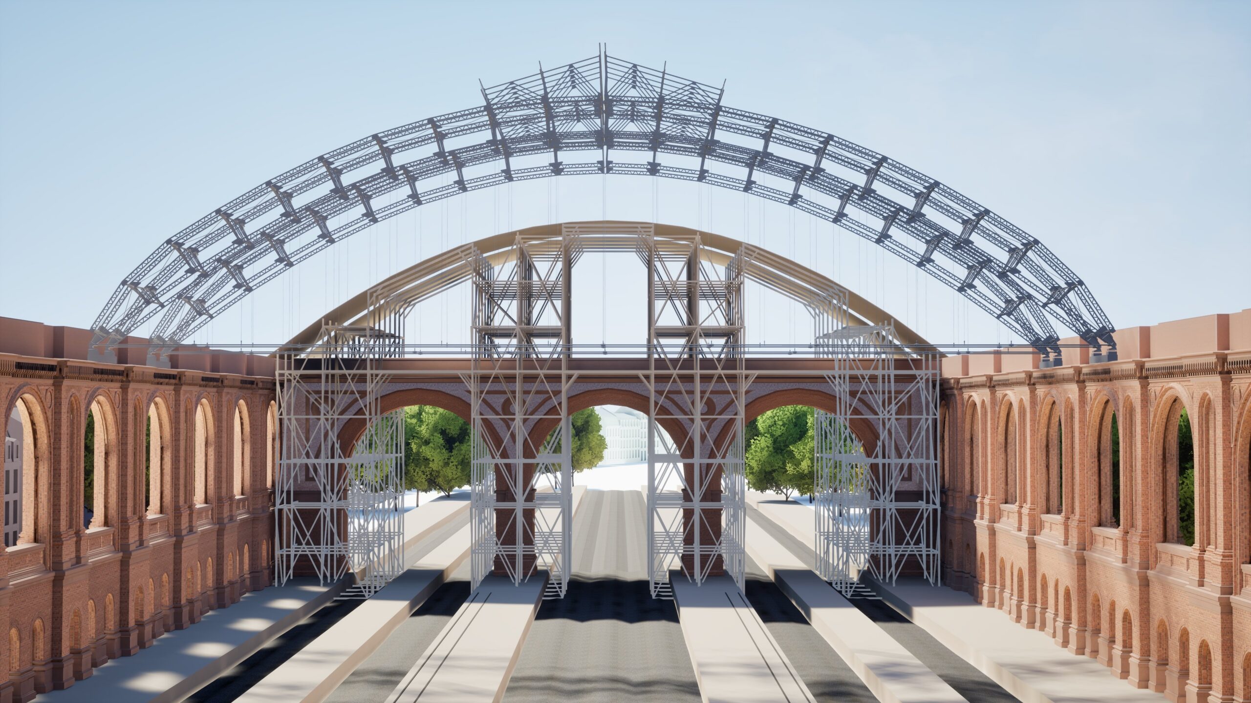
Despite the use of modern lifting technology during its construction, many materials such as bricks and mortar still had to be transported by hand. The “slaking” of lime – physically demanding and health-risking task – was usually left to laborers who, under precarious conditions, relied on night shifts to supplement their meager wages. These and other tasks on construction sites often remained invisible, even though they formed the true foundation for monumental buildings like the “Anhalter” train station.

The example of the “Anhalter” train station illustrates what applies to countless structures worldwide: the history of building is also a history of physical hardship, social inequality, and a lack of recognition for the many who contributed to such major projects. While working conditions, safety standards, and social protections have improved for domestic workers, the situation for temporary and migrant laborers around the world remains characterized by exploitation, unsafe conditions, and low pay. (see UN reports on modern slavery and labor exploitation).

Let’s talk

Collaborate
with us

You have ideas for the content development of the museum and would like to exchange thoughts with us? We’d love to hear from you!

Collaborate as a Museum

Your museum is interested in a partnership? We offer a curated exhibition that we’d be happy to bring to your institution. Get in touch – we look forward to working together!

Become
a Partner

You’re passionate about structural engineering and believe in the importance of sharing it with others? We have big plans and are looking for committed partners. We’d love to hear from you!