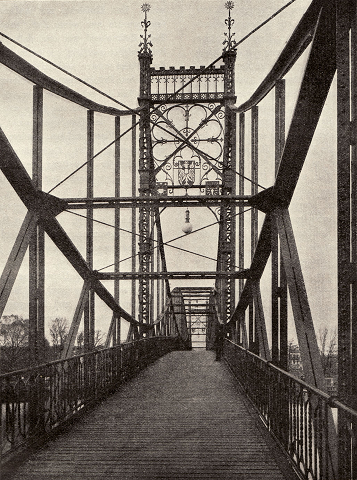
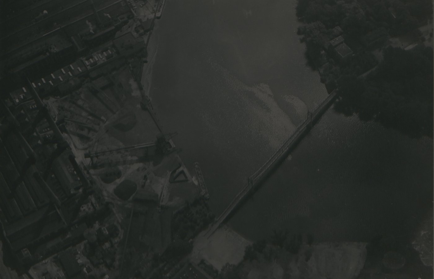
NEW STRUCTURE RECOVERED: The Berlin "Bauakademie" has been online since April 20. Enjoy exploring it!

The

old 
“Kaisersteg”

The Old “Kaisersteg” is an elegant, slender pedestrian bridge with an innovative, doubly statically indeterminate structure. Modern calculation methods enabled a safe, long-span design on extremely slim piers, combining aesthetics and engineering excellence.

1897 – 1898

The Old Kaisersteg is completed in just two years. With its elegantly curved and slender iron structure, the bridge is considered a symbol of technical progress and the industrial spirit of optimism in Berlin shortly before 1900 due to its innovative design.

86 m

In contrast to the original proposal of a five-span arch bridge with a main span of 65 meters, engineer Müller-Breslau designs a lightweight three-span bridge with a main span of 86 meters, supported by two extremely slender piers positioned at the quarter points of the Spree River.

Graphic Statics

The bridge is designed as a beam bridge with a central hinge and integrated arch – a structurally indeterminate system that was innovative at the time. Compared to the Gerber beam system commonly used for similar bridges up to that point, the bridge is more complicated to calculate. Such a design can only be calculated and thus realized using the newly emerging method of Graphic Statics – a scale-based, graphic approach to structural analysis.

3 Years

On April 22 1945, the Old “Kaisersteg” was blown up by SS units in an attempt to stop the advance of Allied forces. Even three years later, remnants of the bridge were still obstructing river traffic. At the time, there were no scrapyards capable of storing the large amounts of iron debris.

The Old “Kaisersteg” is an elegant, slender pedestrian bridge with an innovative, doubly statically indeterminate structure. Modern calculation methods enabled a safe, long-span design on extremely slim piers, combining aesthetics and engineering excellence.

The Old Kaisersteg

yr 1898-1945

  • Historical Background
  • History of use
  • Ownership History
  • Architectural Features
  • The Old “Kaisersteg” is built in 1898 as a pedestrian bridge over the River Spree, connecting the rapidly growing industrial districts of Niederschöneweide and Oberschöneweide. Initiated by the Allgemeine Elektricitäts-Gesellschaft (AEG) and the Wilhelminenhof Land Development Company, the bridge symbolizes Berlin’s rapid transformation into an industrial metropolis. Named after Kaiser Wilhelm I, it represents both technological progress and monarchical prestige.
  • Originally built as a pedestrian bridge, the Old “Kaisersteg” primarily connects workers’ residential areas with the AEG industrial facilities in Oberschöneweide. In 1945, it is destroyed during World War II and not rebuilt afterwards. A modern replacement is constructed in 2007.
  • The Old “Kaisersteg” is jointly financed and constructed by the Wilhelminenhof Land Development Company and AEG. In November 1898, it is transferred into municipal ownership. Today, its successor structure is public infrastructure owned by the City of Berlin.
  • The Old “Kaisersteg” is a slender iron structure with a main span of 86 meters, which was unusually large and elegant for its time. With its small number of pillars and high clearance height, the bridge design specifically considers the requirements of shipping. The clear lines combine the course of a catenary curve with that of an arch, making it an innovative and unique structure in both technical and design terms.
1-4

Dive into the structure of the Old "Kaisersteg"

Click on the feature buttons and discover original drawings, photos, videos and explanations that tell you a story about the Art of Engineering.

The shape of the bridge
The basic static principle
The Pier Load Bearings
The central hinges
The roller bearing with uplift restraint
The construction process

The shape of the bridge

The basic static principle

The Pier Load Bearings

The central hinges

The roller bearing with uplift restraint

The construction process

The shape of the bridge

The basic static principle

The Pier Load Bearings

The central hinges

The roller bearing with uplift restraint

The construction process

The shape of the bridge

The Old “Kaisersteg” was built with only two piers – a decision that was made during the competition in order to minimize disruption to traffic on the river Spree. Originally, a bridge with four piers was planned, but the engineers designing it developed a three-span system with an exceptionally large central opening spanning 86 meters instead. The two side spans are each about half as wide. The very slender piers are arranged at the river's quarter points, contributing to the bridge's particularly elegant appearance.
The lower edge of the superstructure is located at the abutments approximately 4.10 m above the average water level and rises evenly to 9.70 m towards the center. Even directly next to the piers, this leaves a clearance height of around 8 m. The chosen design allows even larger steamships to pass through without having to lower their funnels.
The upper chord of the bridge, which runs over the tops of the piers, is not based on simple shapes such as circular or parabolic segments, but rather the shape of the chord follows the ideal line of a catenary (rope line) under variable loads. The course considers the variable inner forces from the apex to the supports and results in a structurally particularly efficient and at the same time visually harmonious girder profile. The compression arch inserted in the middle section, on the other hand, follows a parabolic shape.
To determine the belt line, several chain lines were calculated to represent different load distributions. The calculations were performed with high precision – the ordinates were determined to three decimal places and then recorded on a large scale. This so-called ‘chain line test’ served not only for static verification, but also for aesthetic control of the line design, which Müller-Breslau considered crucial for the effect of the bridge.
The central large span bears the majority of the loads and therefore follows a significantly larger radius rc than the side spans (rs), which primarily serve to retain the central span. Their greater curvature results from this function. The side opening is retained by the abutments on the bank – a structurally advantageous method, but one that results in tensile or lifting forces at the abutment for loads in the middle of the span.
To check the alignment, the bridge geometry was drawn to scale and mounted in a photographic representation of the surrounding landscape and reduced in size. This made it possible to check the visual impact of the girders in their spatial context and ensure the structural harmony of the design. Unfortunately, we do not have this historical photomontage at our disposal.
1/7

The basic static principle

In the 19th century, engineers faced the challenge of building larger bridges economically and safely – while at the same time having limited computing capabilities. Pictured here: the collapsed Tay Bridge – one of the greatest bridge disasters of the 19th century.
Statically determinate structures have an advantage here: they can be solved simply and solely using the laws of equilibrium mechanics. This means, for example, in the case of a single-span beam (A) or a single-span beam with a cantilever (B): 3 mathematical equations to solve 3 unknown reaction forces.
However, long-span bridge structures often cannot be constructed as single-span beams. For this reason, a special support system was developed in the 19th century. It combines three statically determined systems and is still known today as a Gerber beam (named after Heinrich Gerber). It consists of two single-span beams with cantilevers and a suspension beam in the middle.
The statically determined suspension beam is suspended between two statically determined cantilevered systems and connected by joints.
The result: a large bridge system that is completely statically determined and therefore easy to check using mathematical calculations – ideal for large spans with low computational effort. Thanks to the joints and supports, the system can also react flexibly to settlement and temperature deformation without generating additional forces.
An early example of this system is the “Friedrichsbrücke” bridge in Mannheim. Its lower chord truss structure was formally reminiscent of a chain bridge. It thus combined design elegance with a structurally determined system – a prime example of functional Art of Engineering.
The Old “Kaisersteg” bridge echoes the formal elegance of the “Friedrichsbrücke” bridge, which inspired engineer Müller-Breslau, but he followed a modified static principle.
The classic Gerber truss is not used on the Old “Kaisersteg” bridge. Instead of a separate suspension girder, the lower truss girder in the middle section is designed to be completely continuous.
In addition, the engineers add an elegant arch in the middle section, which extends the lines of the truss upper chord and can be assumed to be a compression arch. This stiffens the bridge and makes it less susceptible to deflection and vibration.
The advantages of the Gerber truss are now lost: the static system without suspension beam turns the “Kaisersteg” into a highly statically indeterminate structure – one that could not be calculated with the methods available at the time.
The engineers therefore deliberately modified the system. Initially, the connection between the upper chord of the truss and the pylons on the river piers was designed with horizontal slotted holes. This prevents axial forces from being transferred to the piers via this member. In structural engineering, such members are referred to as zero-force members, as they do not contribute to load-bearing. As a result, two degrees of static indeterminacy are eliminated.
In addition, the truss is interrupted at midspan by a special double connection detail: a spring plate is inserted into the lower chord, and horizontal slotted holes are provided in the upper chord. The left and right truss sections are supported independently by introducing a double hanger at midspan. In contrast, the compression arch above is constructed as a continuous element without an articulated joint.
The objective: Only specific forces should be transmitted through the central hinge. In the upper chord of the truss, only shear forces (V) are allowed, while in the lower chord, only tensile forces (T) are transmitted. In the compression arch, a compressive force (C) acts as a counterforce equal in magnitude to the tensile force in the lower chord. This results in a structural system that is only statically indeterminate to the second degree. Experienced structural engineers can solve such a system by using elasticity equations and graphic statics.
The Old “Kaisersteg” makes its structural system visually legible: the curvature of the chords, the compression arch, and the distinctive arrangement of the hinges reveal the load-bearing concept. This makes the bridge a remarkable example of a built idealized structural model.
1/7

The Pier Load Bearings

The “Kaisersteg” has four support points, of which only one is fixed in the horizontal direction. This fixed bearing, located on the bridge pier, secures the position of the bridge in space. All other bearings are able to move to accommodate length changes due to temperature variations or settlements. This ensures that the structure remains free from restraint forces.
At both pier heads, multiple forces converge: the vertical loads from the truss superstructure and the compressive forces from the pylons, which absorb the redirection forces of the chain chords at their tops. The steel hinge at this point enables all of these forces to be safely and effectively transferred into the masonry.
The historical construction drawing shows it clearly: the fixed bearing on the river pier at Niederschöneweide is designed exactly as known from structural analysis models — as a fixed point with a moment hinge. It resists both vertical and horizontal forces, while bending moments are avoided due to its rotational capacity.
This fixed bearing represents the structural realization of the idealized model. Its precise detailing makes this clearly comprehensible. The forces are collected at the node above the bearing and are transferred from there into the articulated fixed support.
The second river pier towards Oberschöneweide transfers the bridge loads via a hinge and a roller bearing. Here too, the historical plan shows that the construction follows the principles of mechanical theory.
The function of the roller bearing beneath the hinge is immediately apparent: it allows movements freely along the bridge axis. Here too, the detail follows the static symbol — a clear design that makes both load transfer and freedom of movement visible.
1/7

The central hinges

At the center of the bridge, a very special connection detail is installed. This ensures that only selected forces are transmitted at designated points. At the time, this was necessary because without these hinges, the bridge’s structural system would have been highly statically indeterminate and unsolvable.
The hanger connecting the compression arch to the truss at the center of the bridge is designed differently from all other spans. As a double hanger, it splits below the upper connection to the arch. This effectively decouples the left and right truss sections from each other.
The connection in the lower chord is designed to transmit only tensile forces. It consists of a horizontal spring plate that allows the transfer of tensile forces exclusively. In the vertical direction, this plate has no stiffness.
The connection in the upper chord of the truss is designed to transmit only shear forces. For this purpose, a vertical plate is installed on each side. These plates are connected by bolts with horizontal slotted holes, ensuring that no horizontal forces are transmitted. However, vertical forces can be transferred.
At the crown of the compression arch, almost only compressive forces act; therefore, no special hinge needs to be installed here. Due to the described special design of the truss connections at midspan, it is ensured that the compressive force in the arch is equal in magnitude to the tensile force in the lower chord of the truss
This design of the central opening thus behaves as an ideally rigid connection, capable of distributing the moment at midspan of the bridge into a couple of forces. These act as compression in the arch and tension in the lower chord.
1/7

The roller bearing with uplift restraint

Roller bearings are also installed at both abutments on the riverbanks. Since high tensile forces from the tied arches act here as well, these upward-acting forces must be reliably transferred into the bridge abutments. The goal: The tensile forces must not cause the roller bearings to lift off.
A technically sophisticated detail was developed for this purpose: In addition to the roller bearing, a tension rod is installed to absorb the uplift forces at the support.
The tension rod is connected with hinges at the top to the truss and at the bottom to the abutment. The tensile forces from the truss are transferred into the tension rod via a strong, rigid gusset plate. The rod ends in a hinged connection on the bearing plate. The bearing plate itself is anchored into the abutment by two iron rods with a diameter of 35 mm.
The anchorage of the two tension rods ends in the abutment, 4.61 meters below the bearing. There, they are secured by a double-channel steel beam. The anchorage length was chosen so that the self-weight of the masonry above is sufficient to counterbalance the tensile forces.
The pendulum rod absorbs the uplift forces at the end of the bridge and follows the horizontal movements of the structure. This prevents constraints in the longitudinal direction of the bridge. The tension rod acts as a pendulum rod, allowing the support—together with the roller bearing—to be idealized in structural terms as a horizontally movable hinge.
1/7

The construction process

The load-bearing subsoil consists of sharp sand and gravel and lies relatively close to the surface. The river piers were therefore founded on a concrete base slab between sheet pile walls, with the foundation level located approximately 4 meters below the normal water level. The excavation pits were very narrow, measuring only 2.5 m in width and 8 m in length, and the soil was excavated manually using hand tools. The maximum soil pressure was only 3 kg/cm² (equivalent to 300 kN/m²). For the shorter land piers, the excavation could be carried out in the dry with only minimal dewatering, as the foundation level was higher and the loads correspondingly lower.
The piers were constructed from brick masonry using cement mortar. Visible surfaces received cladding: granite at the end faces and red clinker bricks along the sides. To minimize damage from ship collisions, projections and right-angled edges were deliberately avoided. The river piers are narrow and simple in design, featuring rounded bearing stones. The land piers terminate in granite pedestals that extend beyond the masonry and emphasize the transition to the departure ramp.
The approximately 160-ton steel structure was preassembled in four sections on the right bank of the River “Spree”: the two side spans including the portals, and the central span in two halves, the latter initially without the compression arch and suspension rods. For the bridge assembly, a temporary wooden pier, 2 meters wide, was erected in the middle of the river to serve as an additional support during construction. Since the bridge site was located on a river bend and in a heavily trafficked section, it was advantageous to erect only one assembly pier and to float in the bridge sections.
The preassembled bridge sections were floated into place on two firmly connected “Spree” barges. These barges were equipped with strongly braced portal frames. Each bridge section was rolled from the shore onto rails up to the center of the barges, with about 10 meters cantilevering beyond the barge. This floating support structure was then maneuvered in front of the respective opening.
Using pulley blocks, the superstructure was lifted slightly above bearing height, temporarily shored for safety, and then precisely lowered into position. Only afterward were the compression arch and hangers installed. The insertion of each of the four prefabricated bridge sections took just one day, but the repeated assembly and disassembly of auxiliary structures slowed the overall progress. An alternative lifting process using screw jacks or the later installation of the portals would have significantly simplified the construction process.
After the insertion of the last bridge section, the structure was aligned, the central hinge installed, and the compression arch including the hangers erected. Subsequently, the technical equipment was installed: laying of cables, application of the plank decking and railings, as well as the installation of electric lighting.
The bridge was opened for internal factory traffic on October 1, 1898, before being handed over to the municipality of Oberschöneweide as a public thoroughfare in November.
1/7

Explore the structure of the Old "Kaisersteg" in the comfort of your home.

Here you can download the entire VR exhibition of the Old "Kaisersteg" for free.

Pause

WHO MADE THIS PROJECT POSSIBLE?
WE GRATEFULLY THANK

Funding

Click here to access the complete image credits.

Where were the lost structures located? Find them on the map.

Berlin

The “Ahornblatt” Restaurant

This double-curved concrete shell structure enables large spans with minimal material use. Its futuristic form shapes the Berlin cityscape beyond the GDR era.

Berlin

The Berlin “Bauakademie”

This masonry skeleton construction is a prototype building with a uniform column grid, consisting of rib-reinforced vaulted ceilings, masonry columns , and arches, which set standards for economical and functional construction throughout Prussia.

Berlin

The “Anhalter” Train Station

This masonry structure with pin-jointed iron truss arches connects Berlin to the world. A train station whose innovative roof structure, at the time, featured the largest span in Europe.

Berlin

The Old “Kaisersteg”

This iron truss bridge with an arch and central hinge connects two districts of Berlin. With a main span of 86 meters, it was a technical masterpiece of its time and represents innovative bridge engineering of the late 19th century.

Schmehausen

The Cable Net Cooling Tower

The cable-net cooling tower of the Hamm-Uentrop nuclear power plant in Schmehausen is globally unique in its design. The load-bearing network of steel cables replaces traditional concrete structures, enabling an exceptionally lightweight and efficient construction.

Munich

The Munich Glass Palace

This cast steel and glass structure is built in 1854 using innovative industrial manufacturing processes in a very short time. Although intended as a temporary building, it shaped Munich’s reputation as a city of art for over 75 years through its exhibitions.

Weimar

The Hetzer Timber Halls

The timber halls of the company Otto Hetzer AG were based on a construction principle patented in 1906: glued and curved timber elements that enabled large spans – a groundbreaking innovation in timber construction.

Awareness information

Kaisersteg:

To speak of great engineers is also to speak of power, visibility, and the question of whose contributions are remembered.

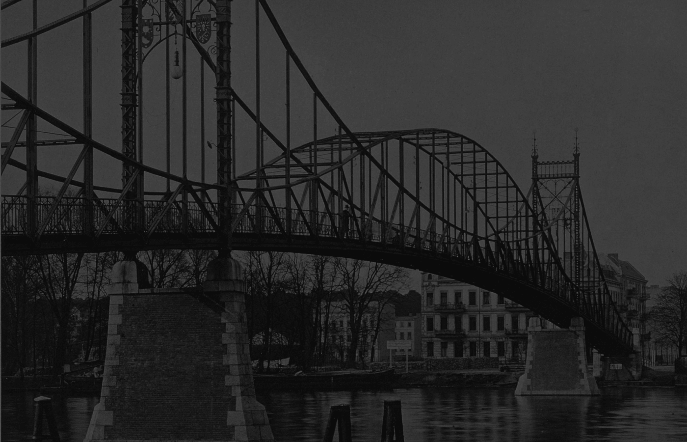
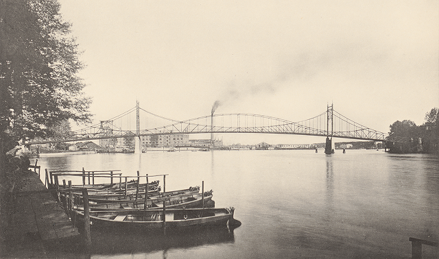
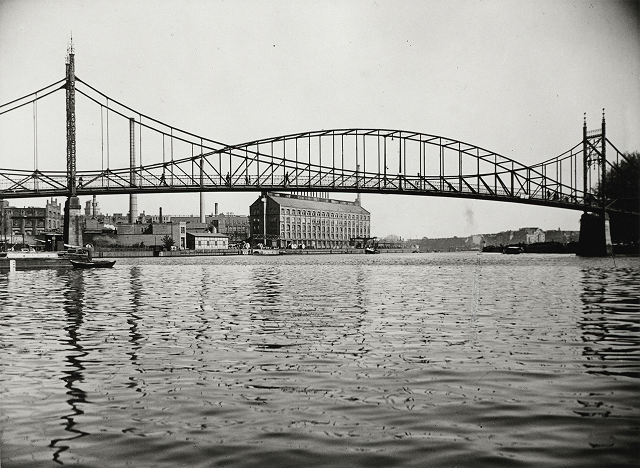
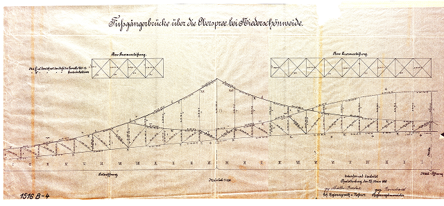
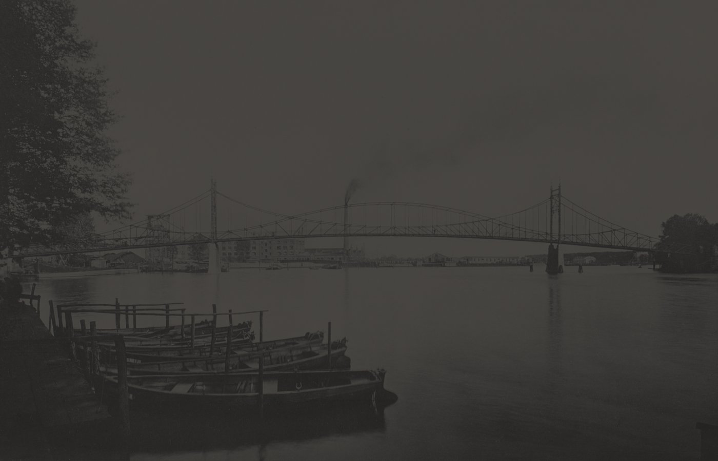
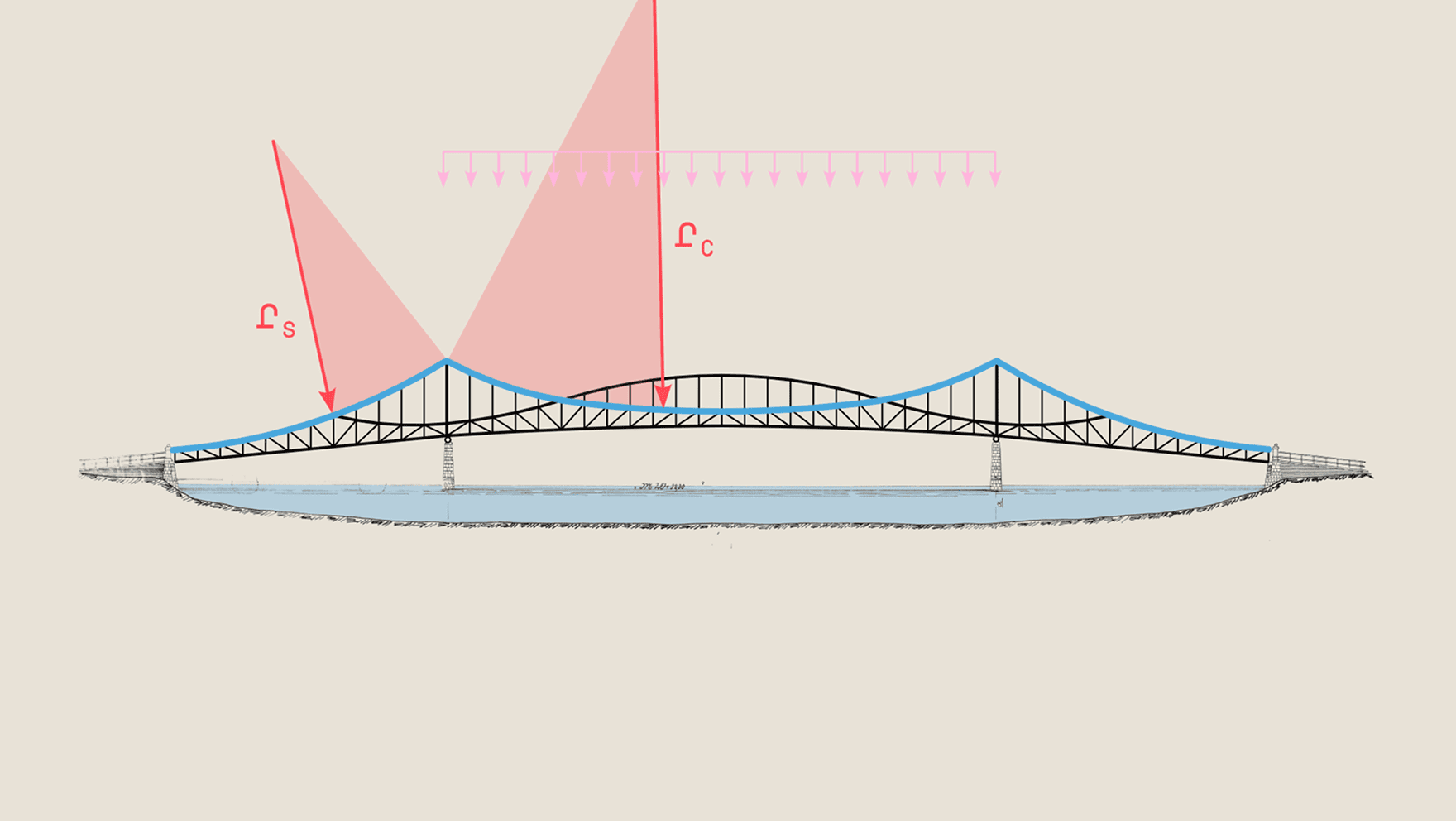
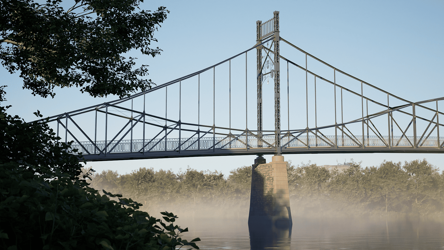
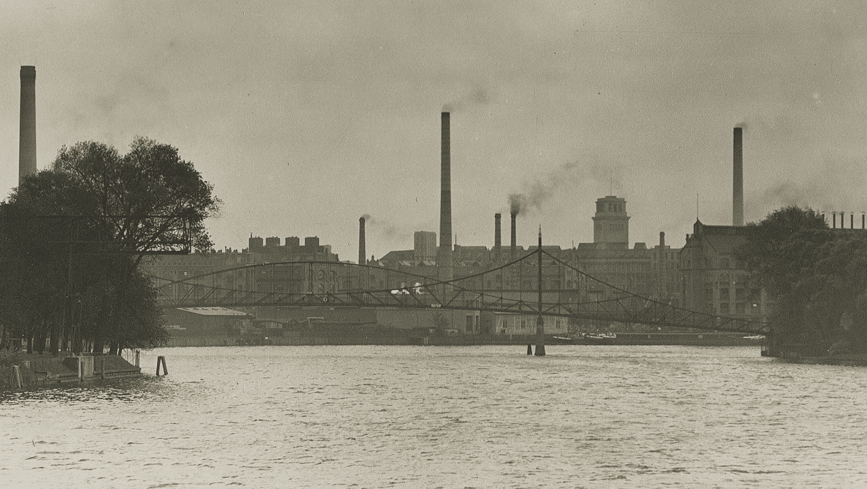
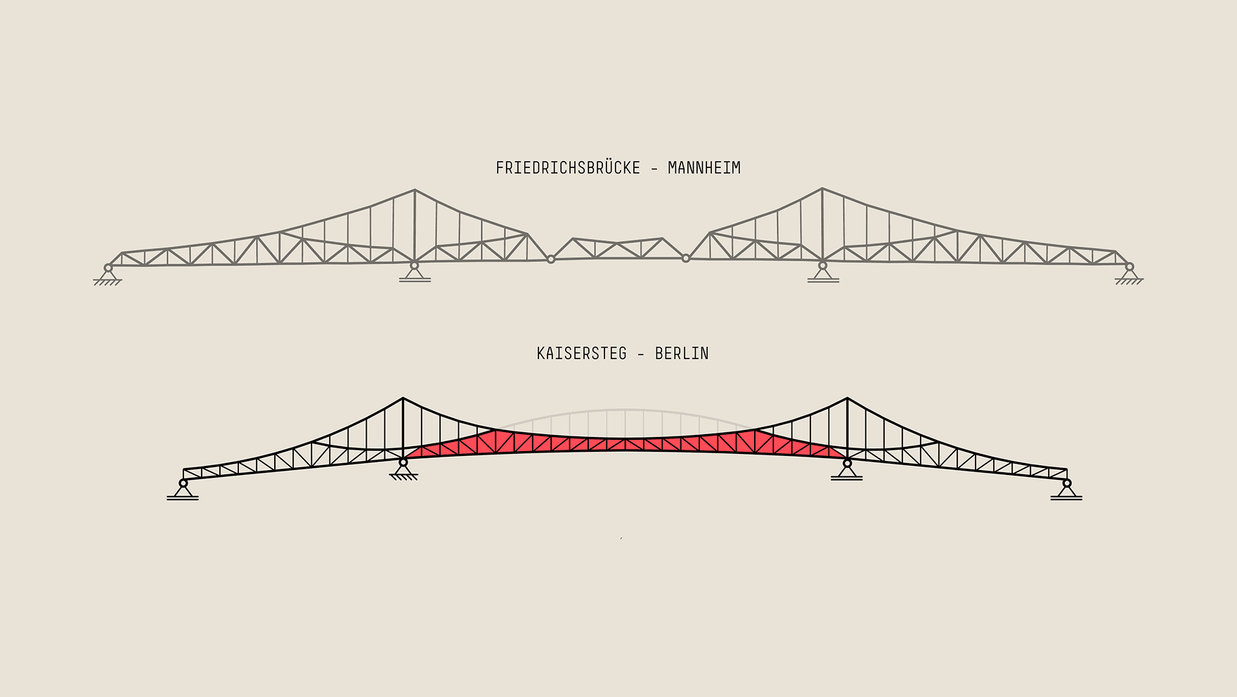
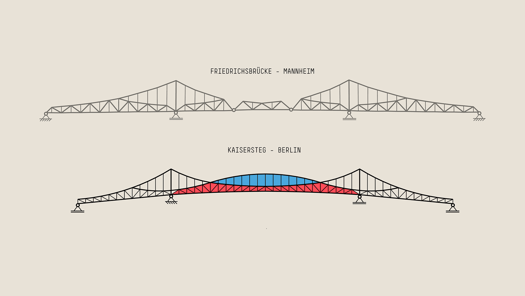
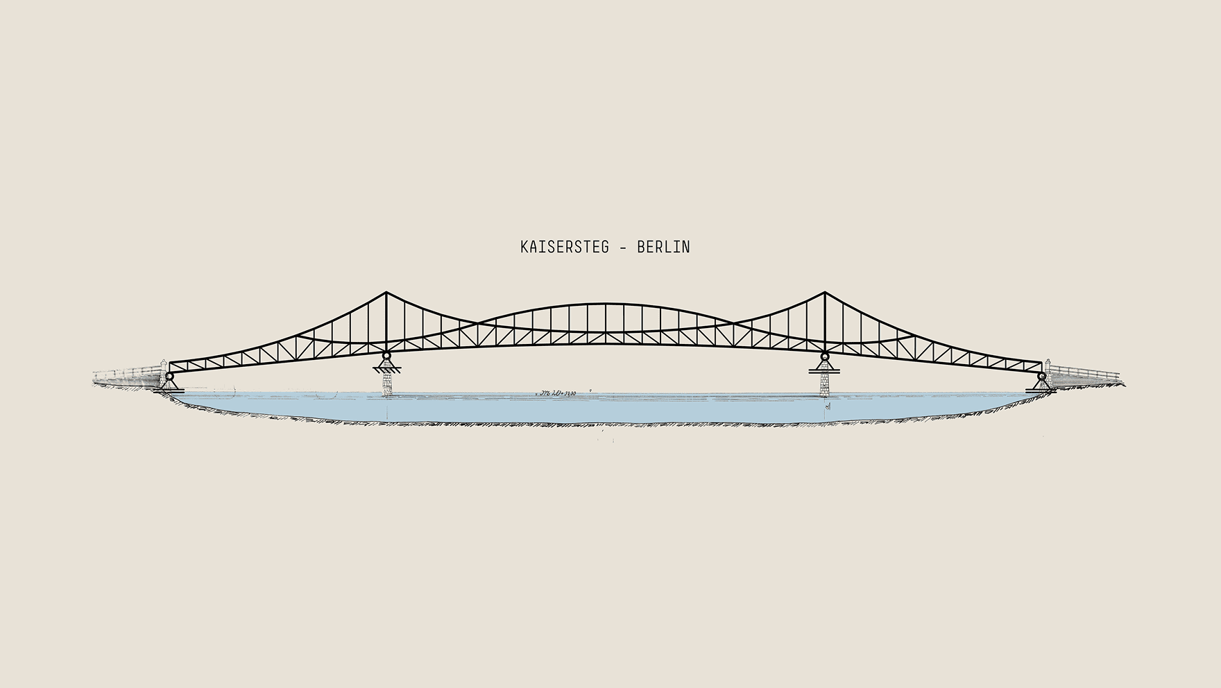
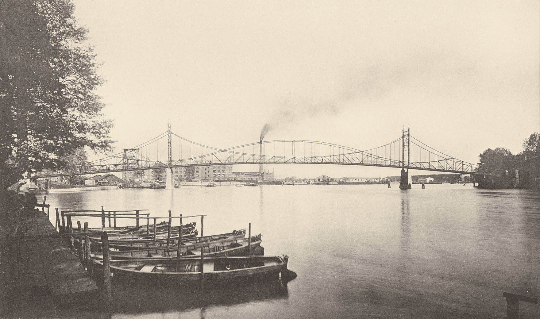
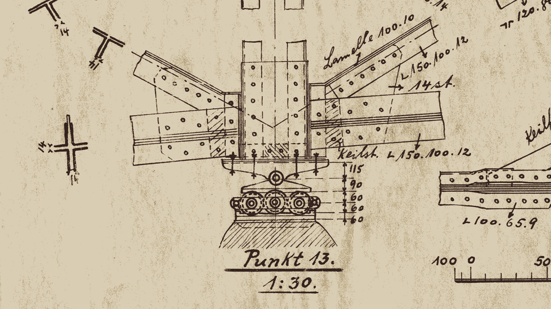
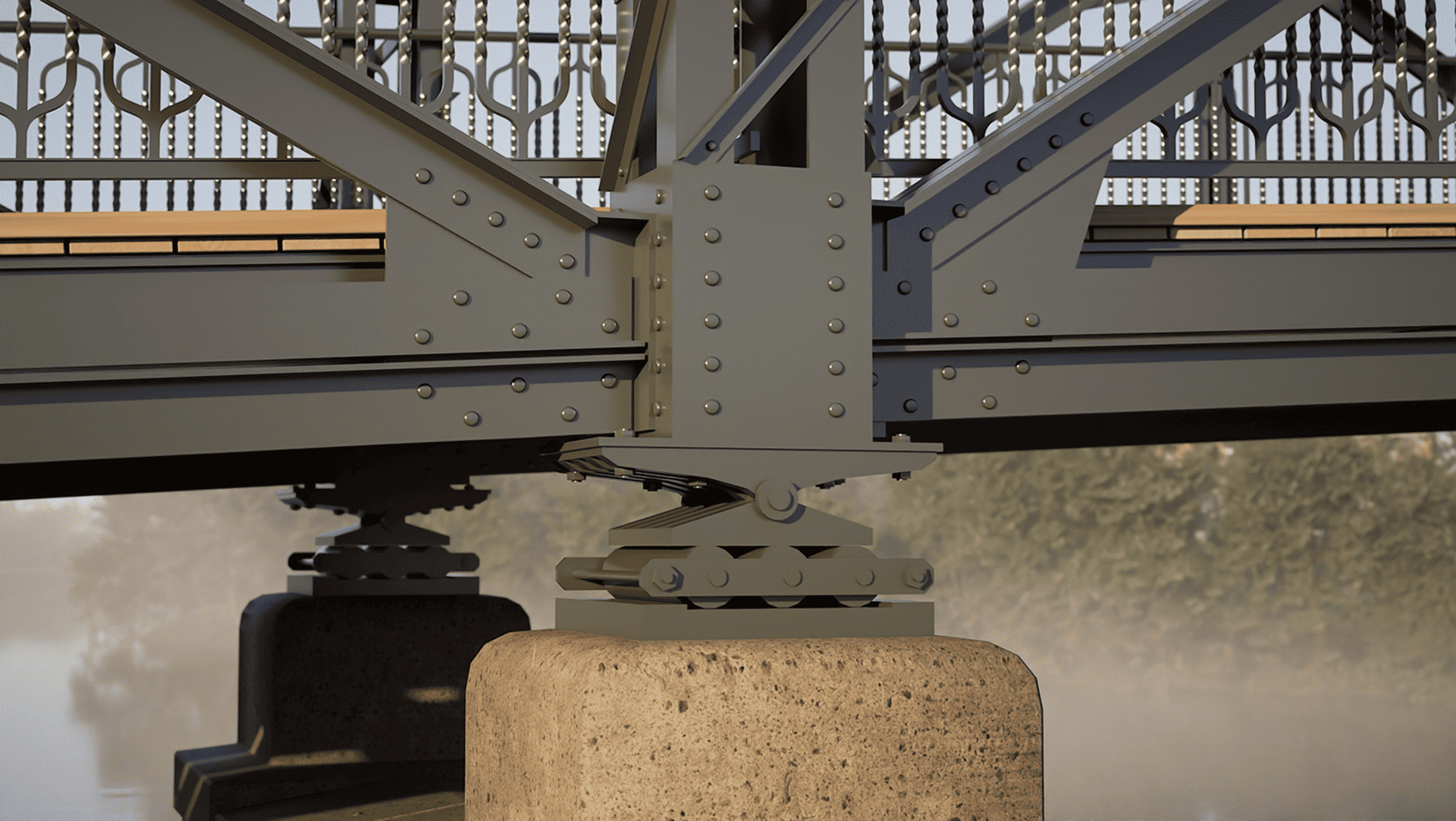
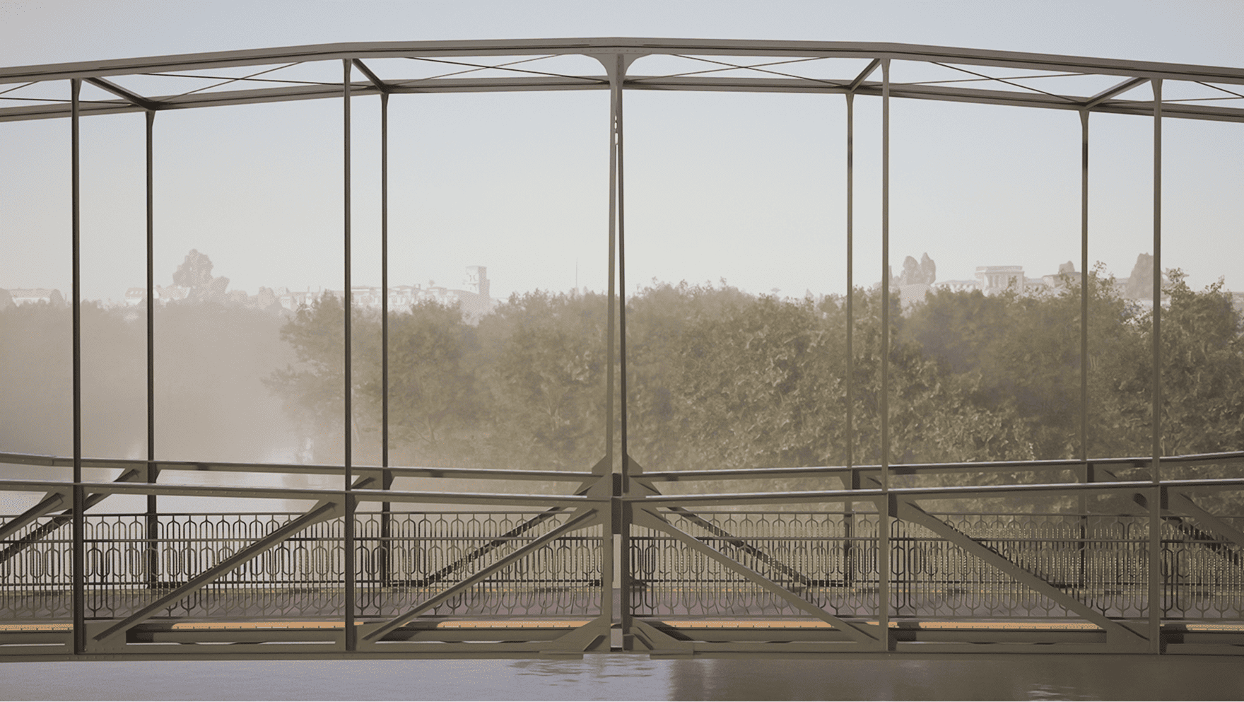
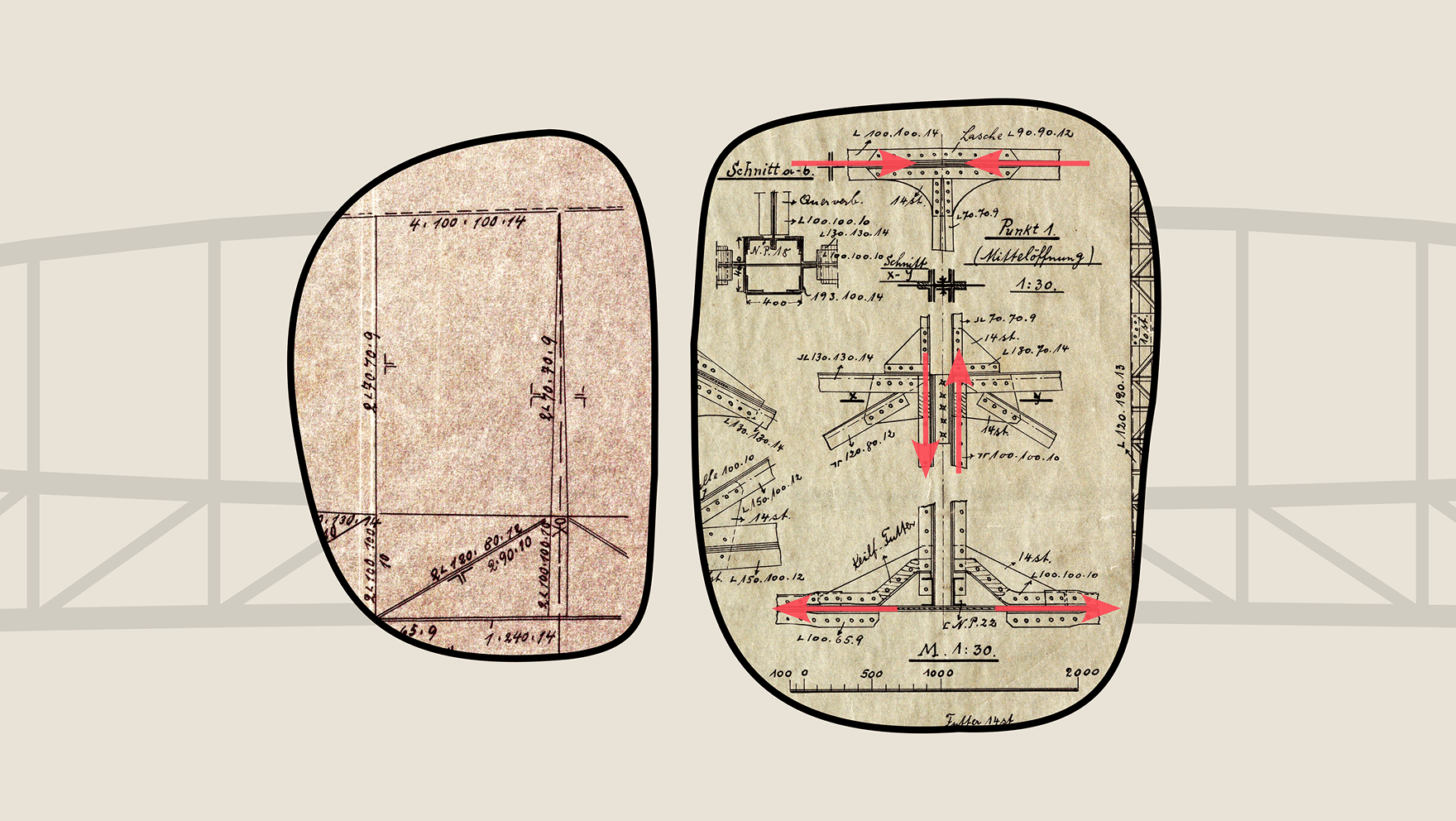
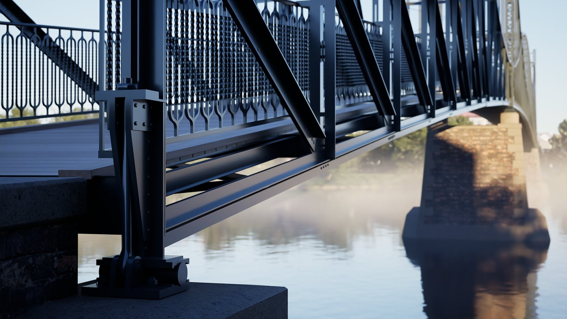
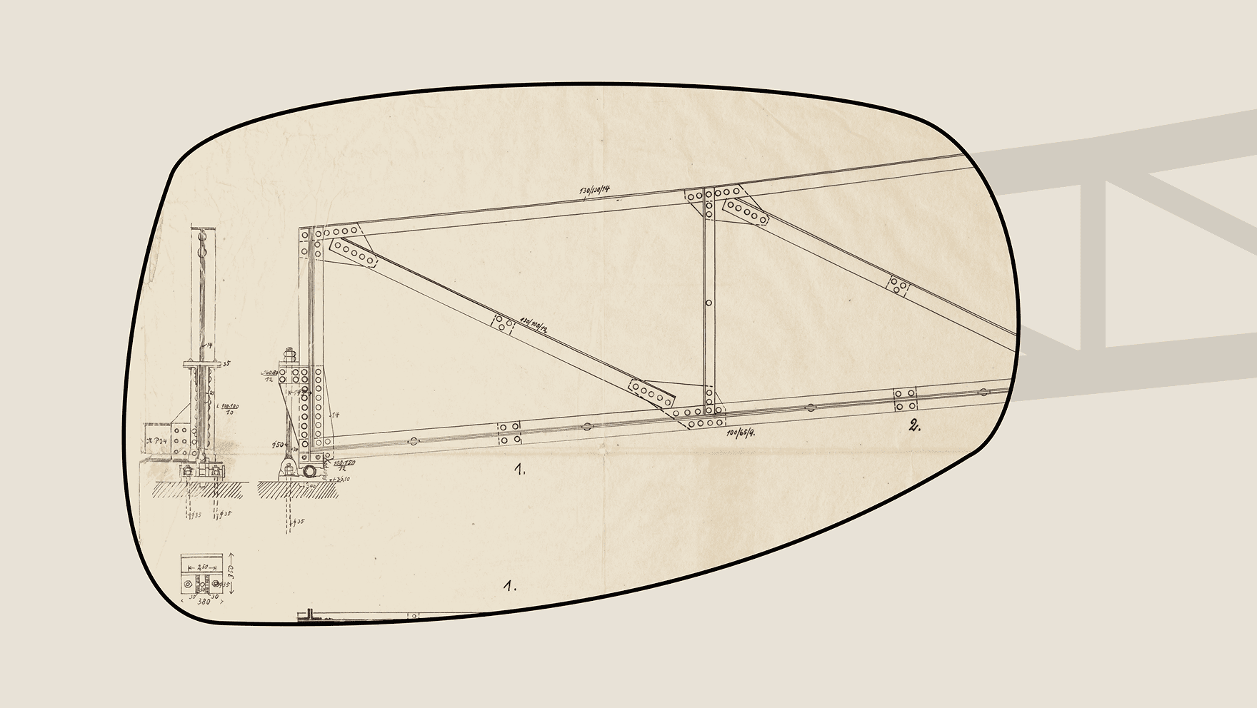
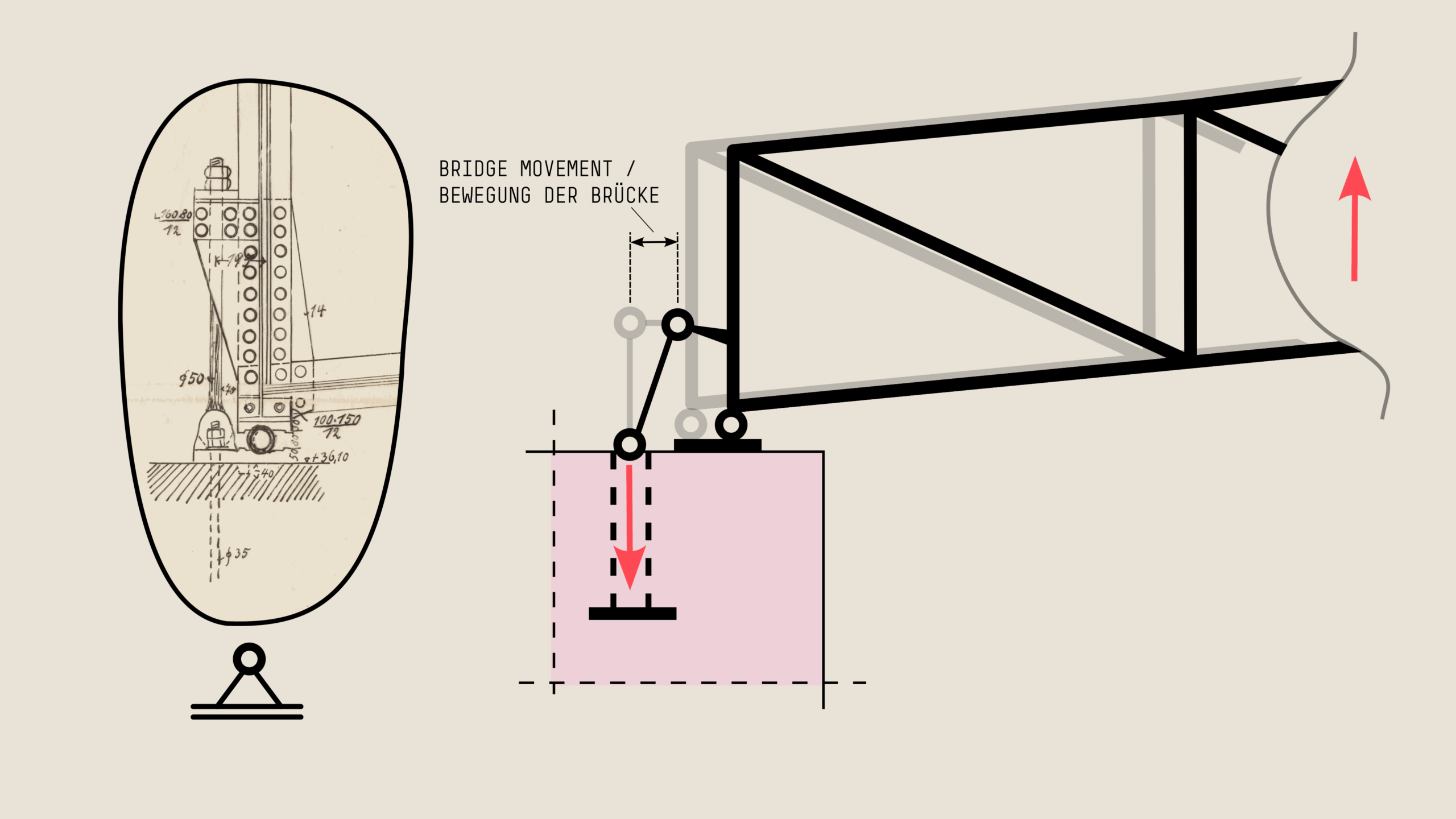
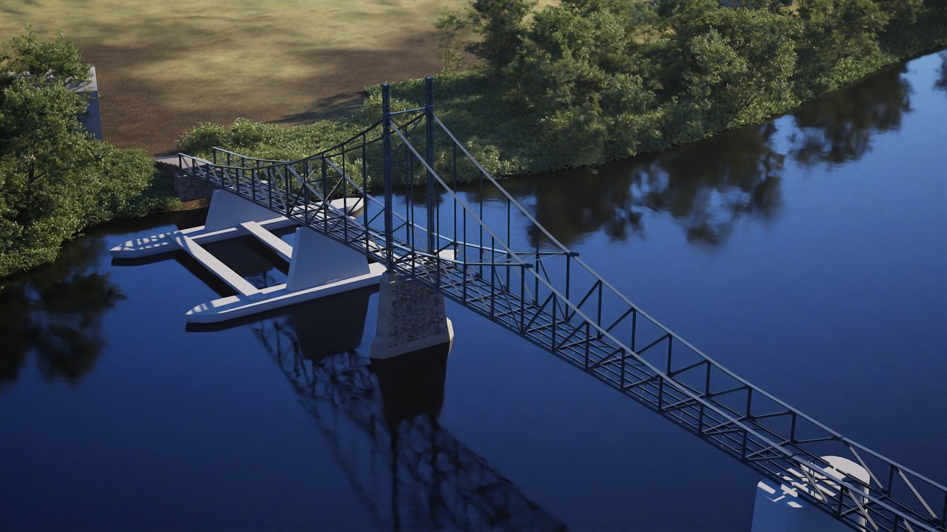
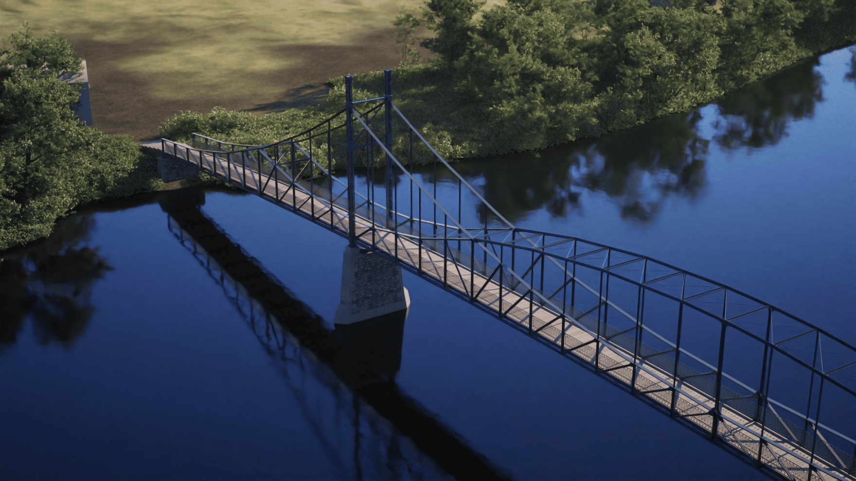
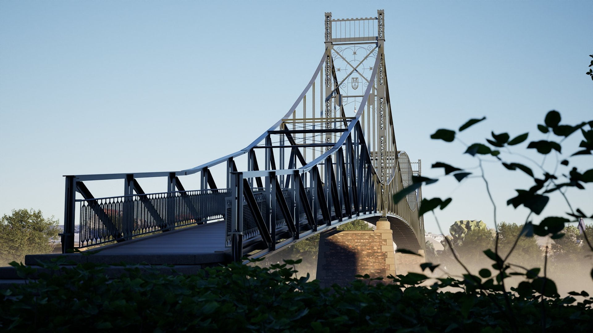
Heinrich Müller-Breslau was one of the most influential civil engineers of his time. The Old “Kaisersteg” in Berlin remains a milestone of modern bridge design and a remarkable example of his technical achievements.

This era—like many fields of science and technology—was deeply shaped by the social structures of its time. Access to education, professional practice, and public recognition was far from equal and, for many groups, particularly women, not a given.

The history of engineering thus reveals not only technical innovation but also how social values and power relations have influenced whose achievements are acknowledged.

Today, cultivating a culture of remembrance means making these connections visible — and rethinking what it means to be a role model: more diverse, more equitable, and more inclusive of the many voices long left unheard. Contemporary initiatives such as “Bauingenieurinnen“ or “Queens of Structure“ contribute to this redefinition, showing how visibility and representation in engineering continue to evolve.

Let’s talk

Collaborate
with us

You have ideas for the content development of the museum and would like to exchange thoughts with us? We’d love to hear from you!

Collaborate as a Museum

Your museum is interested in a partnership? We offer a curated exhibition that we’d be happy to bring to your institution. Get in touch – we look forward to working together!

Become
a Partner

You’re passionate about structural engineering and believe in the importance of sharing it with others? We have big plans and are looking for committed partners. We’d love to hear from you!