NEW STRUCTURE RECOVERED: The Munich Glass Palace has been online since May 3. Enjoy exploring it!

The

Munich 
Glass Palace

The Munich Glass Palace is a pioneering structure of the industrial age, whose load-bearing system - remarkable for its clarity, repeatability, and logical composition - represents an outstanding feat of engineering.

2 months

The iron framework of the Glass Palace was erected in just two months – despite a construction volume well over 150,000 m³ and more than 600 workers on peak days. This impressive level of productivity clearly reflects the exceptional planning and organization behind the project.

2000 Gulden

For the first week of construction delays on the Glass Palace, a penalty of 1,000 gulden per day would have been imposed — rising to 2,000 gulden per day from the second week onward. This was an enormous sum at the time, equivalent to several tens of thousands of euros today, and served as a powerful incentive for the construction company Cramer-Klett to adhere strictly to the schedule.

520

A total of 520 cast-iron trusses formed the impressive backbone of the Glass Palace’s roof and gallery structure, contributing significantly to the building’s lightness and elegance. Despite their delicate appearance, they ensured exceptional load-bearing capacity and structural stability.

June 6, 1931

Over time, the Glass Palace became an important meeting place for artists from around the world. Its destruction by fire on June 6, 1931, was a profound tragedy for Munich’s art scene and marked the first major loss of significant artworks even before the rise of the Nazi regime. With the disappearance of this unique venue, an important era of cultural and artistic diversity in Munich came to an end.

The Munich Glass Palace is a pioneering structure of the industrial age, whose load-bearing system - remarkable for its clarity, repeatability, and logical composition - represents an outstanding feat of engineering.

The Munich Glass Palace

yr 1854 – 1931

  • Historical Background
  • History of use
  • Ownership History
  • Architectural Features
  • The mid-19th century was characterized by a strong belief in technical and economic progress. Bavaria likewise sought to demonstrate its innovative capacity and economic strength. The construction of the Munich Glass Palace took place shortly after the 1851 Great Exhibition in London and was heavily inspired by the Crystal Palace.
  • The Munich Glass Palace initially served as an exhibition hall for industrial, art, and trade fairs, similar to its London counterpart. Over the following decades, it developed into an important venue for contemporary art exhibitions, particularly showcasing works by the “Münchner Künstlergenossenschaft” an artists’ cooperative. Although originally planned as a temporary structure, it stood for over 77 years and became a central forum for contemporary art in Bavaria and beyond.
  • At the time of its completion, the Munich Glass Palace was owned by the Kingdom of Bavaria under the reign of King Maximilian II, and from 1919 onwards, it was owned by the Free State of Bavaria.
  • The Glass Palace was constructed using a state-of-the-art combination of glass and cast iron, enabling rapid construction and large, column-free exhibition halls. The extensive use of glass elements allowed for maximum utilization of natural daylight — a significant advantage given the limited artificial lighting available at the time. Integrated within the cast-iron columns were water pipes that cleverly channeled rainwater from the roof surfaces.
1-4

Dive in to the structure
of the Munich Glass Palace

Click on the feature buttons and discover original drawings, photos, videos and explanations that tell you a story about the Art of Engineering.

Geometry of the Glass Palace
The basic structural framework
The cast-iron truss
The main truss
The columns
The lateral bracing system
The drainage system
The construction phase

Geometry of the Glass Palace

The basic structural framework

The cast-iron truss

The main truss

The columns

The lateral bracing system

The drainage system

The construction phase

Geometry of the Glass Palace

The basic structural framework

The cast-iron truss

The main truss

The columns

The lateral bracing system

The drainage system

The construction phase

Geometry of the Glass Palace

The floor plan of the Glass Palace is based on a clear axial order. The entire structure is symmetrically aligned along both the main longitudinal and main transverse axes, which is evident in both the floor plan and elevation drawings. This clear organization gives the enormous building—even with its length of over 230 meters—a manageable, almost modular readability.
The ground floor is divided into three parallel naves — a central main nave and two adjoining side naves. This structure resembles a three-aisled basilica. The individual naves are rhythmically organized by regularly spaced column grids. In both the transverse and longitudinal directions, this results in a uniform axis spacing of 20 Bavarian feet (5.84 meters).
On the upper floor, galleries run along both sides as continuous walkways following the building’s longitudinal axis. They are supported by cast-iron trusses and serve not only as exhibition space but also as important structural elements for bracing the building. The height offset between the ground floor and gallery level creates a spacious interior arrangement.
The facade of the Glass Palace is organized in a grid pattern by vertical columns and horizontal beams. This regular arrangement allows the use of standardized glass elements, significantly reducing construction time and costs. The building’s transparency makes the structure visible — a revolutionary idea at the time.
The isometric view clearly reveals the hierarchical layering of the building: the main nave rises above the side naves, which in turn are topped by the central dome of the transept. This vertical articulation follows both functional and aesthetic considerations: it allows generous natural lighting and gives the building a monumental presence.
1/7

The basic structural framework

The Glass Palace is a pure iron skeleton structure — columns and beams carry the entire load. The construction was designed for speed: prefabricated components and a clear grid system enabled assembly within a few months, offering a clear advantage over conventional masonry construction.
The main girders are precisely dimensioned: the mixed-material trusses span 23.35 m (80 Bavarian feet) with a height of 1.25 m, and the cast-iron trusses span 5.84 m (20 Bavarian feet) at a height of 1.22 m. The columns are arranged in two stories, with a total height of approximately 18 m in the standard sections.
The vertical roof loads are transferred via the glass surfaces to the trusses and cast-iron trusses. From there, they are carried into the columns, which transfer them to the ground through individual foundations. The force flow is clearly organized — a prerequisite for industrial construction completed in record time.
To resist wind forces, a horizontal bracing system made of iron is used—consisting of diagonal round profiles across three roof levels. The wind bracing stiffens the floor levels. According to a note on the plan, the cross-sections of the round iron vary between 9.0 and 14.6 cm² (interpretation of the poorly legible plan).
The lateral bracing is provided by a frame system with so-called diaphragm action. The trusses and cast-iron trusses act like "two-hinged beams on surface supports." This allows horizontal forces to be absorbed—without the need for massive walls or additional wind bracing.
1/7

The cast-iron truss

The cast-iron trusses are located beneath the roof surfaces as well as below the upper gallery. They connect the cast-iron columns within the grid system—except at the outer enclosing walls—and function as load-collecting structural members. A total of 520 units are used.
Each cast-iron truss consists of a continuous frame with a T-shaped cross-section, subdivided into four rectangles by three vertical members with a cruciform profile. These panels are diagonally braced. The gallery load-bearing trusses are additionally reinforced at the top chord with fish-belly shaped ribs.
The cast-iron trusses were produced as single castings. They are exactly 5.63 m long and 1.17 m high. They are designed to fit into the building’s 20-foot grid system and integrate seamlessly both visually and structurally into the load-bearing concept. Despite their delicate construction, they carry considerable loads.
Cast iron behaves predictably under compression but unpredictably under tension. Due to the calculation methods of the time, the load-bearing capacity was therefore not determined solely by calculation: the heaviest truss weighs 830 pounds. The proof of load-bearing capacity was performed practically—through targeted load tests on the construction site.
The cast-iron trusses were loaded with a test weight of 350 hundredweights. Crucially, after unloading, the truss had to fully return to its original shape. The measured deflection provided insights into the quality of the iron and allowed for a reliable assessment before installation.
The cast-iron trusses are bolted to the columns. Cast-on lugs on the columns ensure precise assembly. By bolting at the top and bottom chords, a rigid frame corner can be created - essential for the bracing of the skeleton structure.
1/7

The main truss

The trusses span the nave and the central aisle, resting on columns spaced 80 Bavarian feet (approximately 24 m) apart. They support the glazed roof surfaces and enable large column-free interior spaces—a key architectural feature of the Glaspalast.
Each truss is 23.14 m long and 1.25 m high. For rainwater drainage, it is cambered by 0.175 m at the center. The structure consists of wrought iron flat bars in the bottom chord and angle irons in the top chord, with 17 cast-iron vertical members and 16 crossed braces in between.
The cross braces consist partly of wrought iron flat bars and partly of solid oak timber members. They are bolted and riveted to connect the longitudinal members. This hybrid construction of cast iron, wrought iron, and wood was designed not only for functionality but also for material efficiency.
A single truss carries a dead load of 2,500 kg and an additional live load of 14,500 kg. The structure is designed to be robust enough to function safely under full load, while remaining light enough to maintain the delicate construction.
The main trusses were tested on site by applying uniform loads. The deflection measured 19.5 decimal lines (4.25 mm), and after unloading, only 1.5 decimal lines (0.33 mm) of residual deformation remained. This confirmed the elastic recovery and the material quality of the installed components—significant plastic damage was to be avoided.
Part of the enclosing wall of the transverse wing rests directly on the trusses of the central nave. However, these trusses can only carry 12,000 kg, while the actual load—including snow, roof, and masonry—amounts to 70,000 kg. To avoid overloading, the majority of the load (58,000 kg) is transferred via a separate support system.
The enclosing wall itself is designed as a load-bearing Howe truss. The central wall columns are connected to their neighboring columns by double diagonal tension rods, which are lap-jointed and bolted at the top and bottom. This creates a rigid truss structure that carries the main load independently of the underlying trusses.
To prevent the Howe trusses from sagging under load, Ludwig Werder developed a device for prestressing the tension rods. This measure ensures that the structure remains stable under load and reliably carries the required portion of the load.
1/7

The columns

Two standardized cast-iron column types were used in the Glaspalast. The exterior columns have a hollow, square cross-section with cast-on corner reinforcements. The interior columns are octagonal with four attached round rods. Depending on the installation location, elements of varying lengths are bolted together to achieve the required structural height.
The columns mostly consist of two or more parts bolted together vertically. At the connection points, brackets for cast-iron trusses and other components are already provided. Especially along the exterior walls, an additional 6 Bavarian foot (approx. 1.75 m) high section is used to provide a stable connection for the gallery level.
The columns are mounted on cast-iron bases resting on a total of 298 individual foundations. These bases feature a rhombus-shaped bearing plate with reinforcing ribs and collars for bolting. Integrated pipes channel rainwater into an underground drainage system.
The individual foundations consist of stepped brick masonry. To compensate for height tolerances in the masonry, Ludwig Werder developed a precise leveling device: using sleeve pipes and screws, the column base can be accurately adjusted to the correct level—an innovative solution for fast and economical assembly
From a modern perspective, the columns of the Glass Palace appear exceptionally slender, with long effective buckling lengths and only limited cross-sectional reserves. The rigid connections with the cast-iron trusses introduce additional bending moments, increasing the risk of flexural buckling. Such effects are scarcely documented in the surviving structural calculations; however, the problem was well known at the time and, as evidenced by the building standing for over 75 years, was correctly accounted for.
1/7

The lateral
bracing system

Every load-bearing structure requires an effective bracing system to withstand lateral forces such as wind – and the Glass Palace is no exception. The historical documents contain only fragmentary structural calculations, which makes certain interpretations necessary. Particularly interesting is the bracing concept used in the standard section of the longitudinal halls.
The frame structure is based on a statically indeterminate system with multiple degrees of redundancy. Such systems offer high load-bearing reserves because they allow for plastic deformations without immediate structural failure. At the same time, they involve uncertainties: restraints, for example due to thermal expansion, are difficult to calculate and can introduce unintended internal forces.
Two connection variants between the truss and the columns are considered during the design phase:
- Pinned connection, to accommodate thermal expansion and keep the slender columns free from bending moments.
- Rigid connection, creating a continuous frame – beneficial for bracing, but riskier due to the danger of lateral-torsional buckling.
The exact execution cannot be fully verified. However, indications of slotted bolt connections in the upper chord suggest that a pinned connection was likely implemented.
The structural system in the standard section of the longitudinal aisles is assumed to be a two-hinged truss supported on planar bearings. This system consists of the main truss that is articulated at both ends and rests on two lateral load-bearing elements acting as structural diaphragms.
The shorter cast-iron trusses are rigidly connected to the columns over two stories via their top and bottom chords. These connections form a stiffening surface that acts as a structural diaphragm, providing the frame with its horizontal rigidity — the so-called 'planar bearing'
At the connection between the upper chord of the main truss and the columns, detailed drawings show a horizontally slidable bolted joint. This prevents tensile forces resulting from negative frame corner moments from being transferred into the columns. This solution ensures the hinge behavior and prevents critical loading of the columns due to unwanted bending moments
The chosen construction demonstrates a high level of engineering expertise. Despite incomplete records of calculation models by today’s standards, a structural system was developed that remained functional for over 75 years. The combination of a rigid substructure and a hinged roof framework represented an innovative solution for lateral bracing at the time.
One problem remains: The tall, slender columns are highly susceptible to flexural buckling due to their geometry, especially under additional moment loads from the frame corners. Furthermore, the model assumed a fixed support at the foundation, which has not been proven in reality. From today’s perspective, this is a very daring design, but the planners relied on their expertise (… and the safety margins provided by the statically indeterminate system).
1/7

The drainage
system

The drainage system of the Glass Palace was far more than just a functional detail — it was an integral part of the overall structural concept. Instead of visible downpipes or external drainage channels, rainwater was invisibly channeled through the structure itself. This sophisticated system connects the roof, columns, and foundations into a continuous conduit network that is both architecturally elegant and technically advanced. The following illustrations and explanations show how rainwater was guided from the glass roof, through the columns, down to underground reservoirs.
For the roof drainage, the Glass Palace employed the proven “ridge and furrow” system, which was already used in the London Crystal Palace. The principle involves alternating inclined roof surfaces that quickly and efficiently collect and channel rainwater. This design was originally developed for greenhouses but was systematically applied here to a large-scale building.
Rainwater from the roof surfaces was collected directly into gutters positioned above the girders and cast-iron trusses. From there, it flowed through openings into the hollow cores of the cast-iron columns, which served as vertical downspouts.
The interior of the hollow-cast columns was purposefully used for drainage. Particularly ingenious: the columns rested on specially designed base plates that directed the water into the foundation without compromising the structural function.
Beneath the ground floor, a branched pipe system was installed that collected rainwater from all areas of the building and directed it towards the collection basins.
Three underground water reservoirs distributed along the building’s longitudinal axis collected the drained rainwater. These presumably served not only as storage but also for controlled drainage or utilization of the water.
Water played an important role in the Glass Palace: Inside, there were three fountains, with the central one serving as a key element of the spatial design, as shown in a historical drawing.
1/7

The construction
phase

Der Bau des Glaspalast in München ist ein Symbol industrieller Präzision und bautechnischer Pionierleistung. In nur 9 Monaten wird die Bauausführung organisiert, es werden 298 Säulen, 520 Sprenggitter und 35 Sprengwerke produziert, nach München transportiert und dort montiert. An den produktivsten Tagen zählte die Baustelle über 600 Arbeiter.
On August 22, 1853, chief architect August von Voit received the commission and drafted the contract with the construction company Cramer Klett (September 11, 1853). An ambitious timeframe was agreed upon: the Glass Palace was to be completed by June 8, 1854. In case of delay, a penalty of 1,000 gulden per day was imposed during the first week, increasing to 2,000 gulden per day from the second week onward.
On September 24, 1853, Voit took over the construction management, supported by draftsmen and an engineer. The detailed workshop planning at Cramer Klett proceeded in parallel with the site preparation and was led by Johann Ludwig Werder.
In mid-October (October 17, 1853), the foundation work began. By the end of the year, all foundations were completed and the column bases were built in. Using a device developed by Werder, the column feet could now be rotated and leveled on the bases. This adjustment allowed for precise assembly despite uneven ground.
On January 18, 1854, the erection of the scaffolding began. Possible ground settlements required a lightweight and flexible scaffolding. After some criticism, the structures were additionally reinforced.
To deploy as many workers as possible simultaneously, construction began at multiple locations. First, the transept and the eastern wing were scaffolded. Their scaffolding timber was later reused for the western wing to save materials. The longitudinal nave sections were erected without scaffolding, using cranes and platforms running on rails. After assembling the iron and wooden components, the walls were glazed in a rhythmic sequence — an efficient process that saved on scaffolding costs.
On February 27, 1854, the first 11 columns were installed, the first truss was tested, and less than two weeks later it was mounted. This marked the start of the meticulously planned and precisely timed assembly of the structure. With just under 300 workers at the beginning of March, the workforce had already doubled to 600 by the end of the month.
The progress made on the construction is due to a piecework-like construction process. To enable this, two large work sheds over 35 meters long were built in the central transept. Here, the main trusses were assembled, the cast-iron trusses cut to length, and their load-bearing capacity tested. At the same time, the diagonal rods for the roof bracing were tensioned.
After the first main truss was tested for its load-bearing capacity, the first of 35 trusses could be mounted with cranes on April 1, 1854. The rail-based lifting technology allowed for fast and safe assembly, so that just four days later, eleven trusses were already installed.
At the end of April, Voit confirmed the completion of the structural shell by authorizing the release of the remaining payment to the company Cramer Klett. The iron skeleton was thus erected in just two months.
Glazing of the building had already begun on April 18, 1854, following a systematic, assembly-line process.
The official handover to the Industrial Exhibition Commission (client) took place as contractually agreed on June 8, 1854. The galleries were completed just one week earlier, and the glazing was finished one day before the handover.
1/7

Explore the structure of the Munich Glass Palace in the comfort of your home.

Here you can download the entire VR exhibition of the Munich Glass Palace for free.

Pause

WHO MADE THIS PROJECT POSSIBLE?
WE GRATEFULLY THANK

Funding

Click here to access the complete image credits.

Where were the lost structures located? Find them on the map.

Berlin

The “Ahornblatt” Restaurant

This double-curved concrete shell structure enables large spans with minimal material use. Its futuristic form shapes the Berlin cityscape beyond the GDR era.

Berlin

The Berlin “Bauakademie”

This masonry skeleton construction is a prototype building with a uniform column grid, consisting of rib-reinforced vaulted ceilings, masonry columns , and arches, which set standards for economical and functional construction throughout Prussia.

Berlin

The “Anhalter” Train Station

This masonry structure with pin-jointed iron truss arches connects Berlin to the world. A train station whose innovative roof structure, at the time, featured the largest span in Europe.

Berlin

The Old “Kaisersteg”

This iron truss bridge with an arch and central hinge connects two districts of Berlin. With a main span of 86 meters, it was a technical masterpiece of its time and represents innovative bridge engineering of the late 19th century.

Schmehausen

The Cable Net Cooling Tower

The cable-net cooling tower of the Hamm-Uentrop nuclear power plant in Schmehausen is globally unique in its design. The load-bearing network of steel cables replaces traditional concrete structures, enabling an exceptionally lightweight and efficient construction.

Munich

The Munich Glass Palace

This cast steel and glass structure is built in 1854 using innovative industrial manufacturing processes in a very short time. Although intended as a temporary building, it shaped Munich’s reputation as a city of art for over 75 years through its exhibitions.

Weimar

The Hetzer Timber Halls

The timber halls of the company Otto Hetzer AG were based on a construction principle patented in 1906: glued and curved timber elements that enabled large spans – a groundbreaking innovation in timber construction.

Awareness information

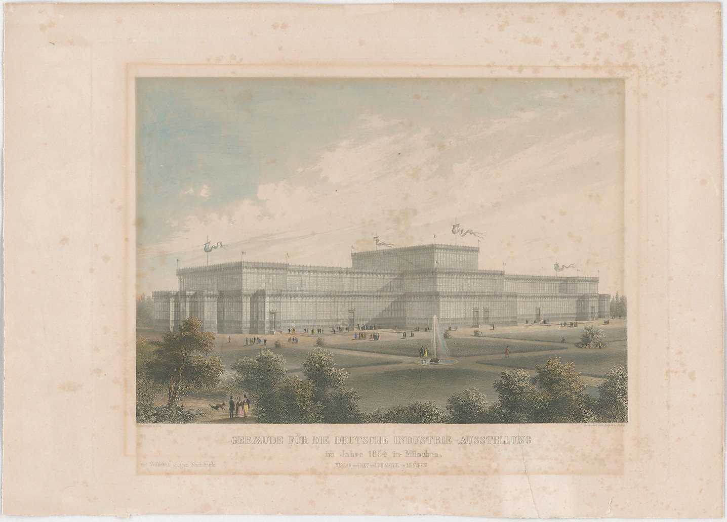
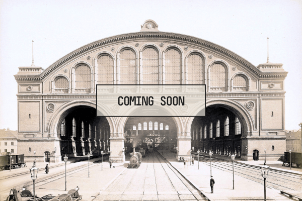
Münchner Glaspalast:

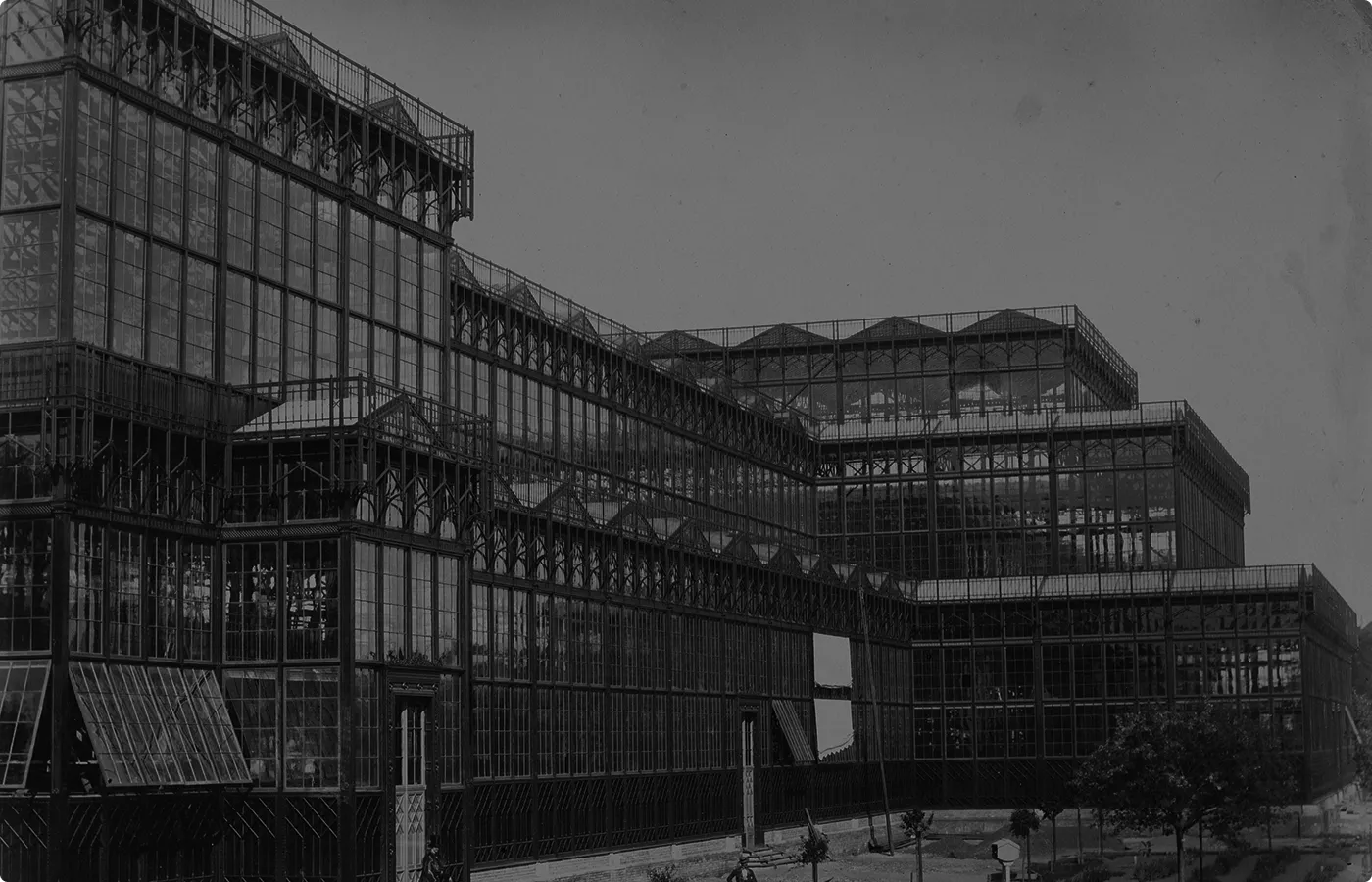
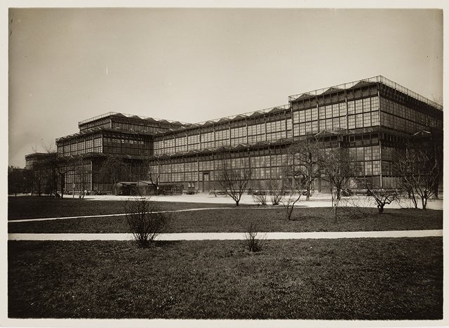
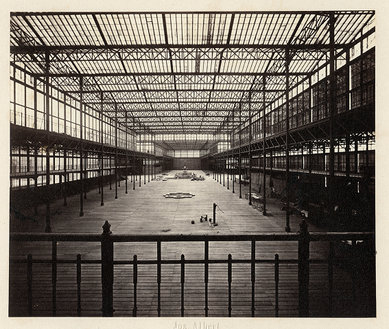
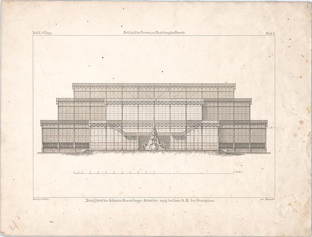
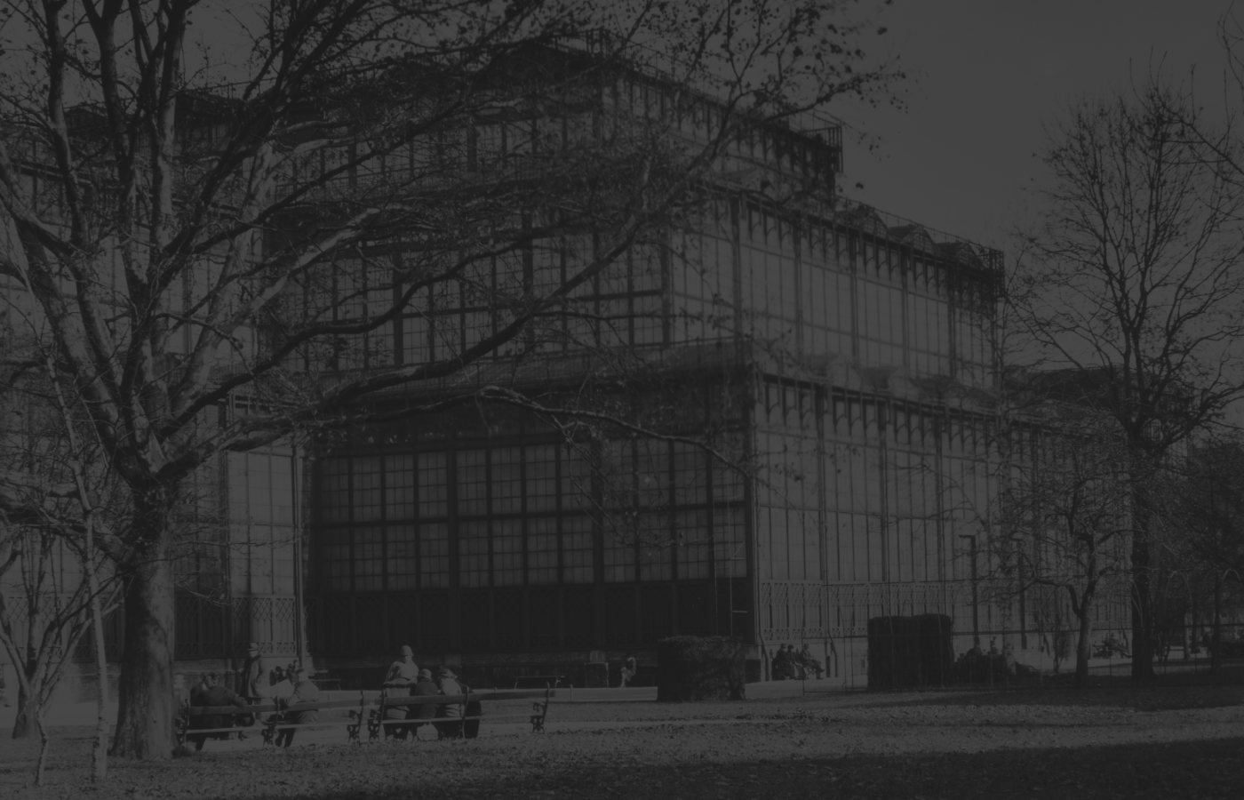
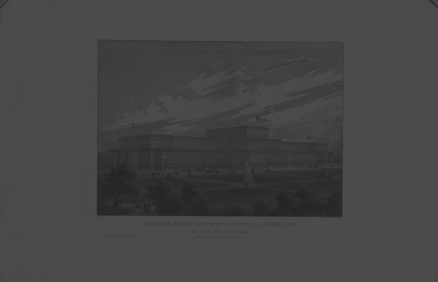
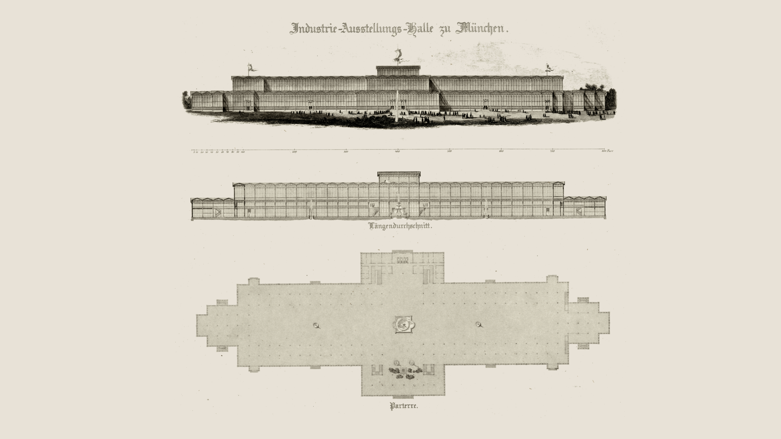
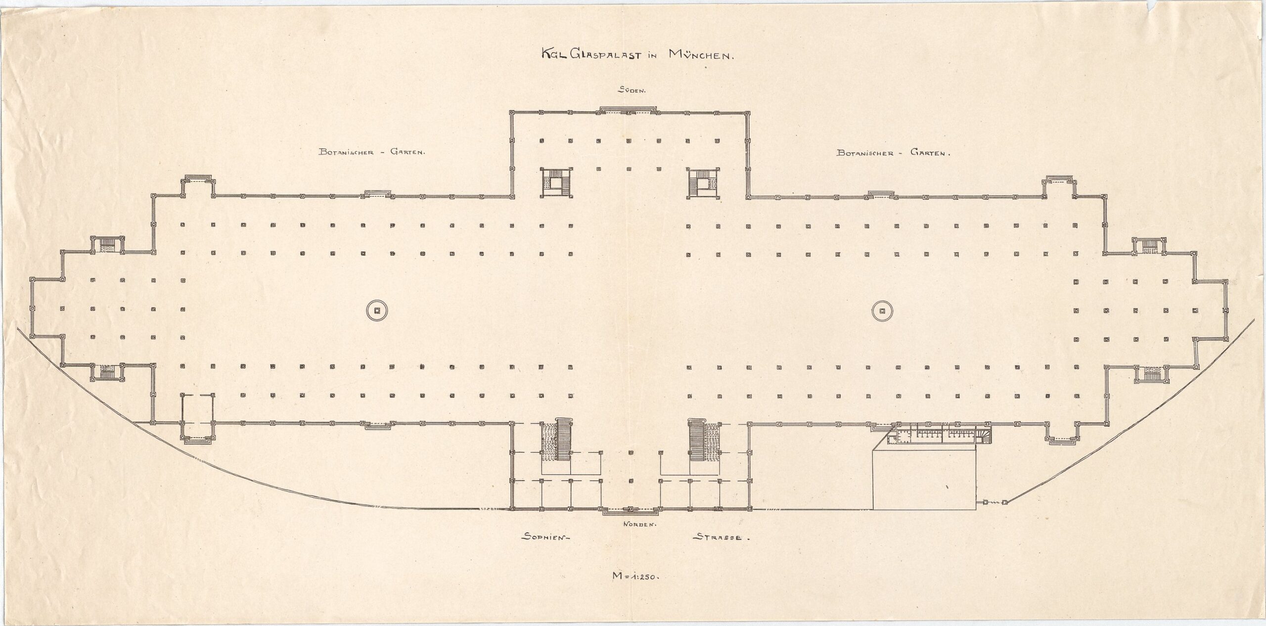
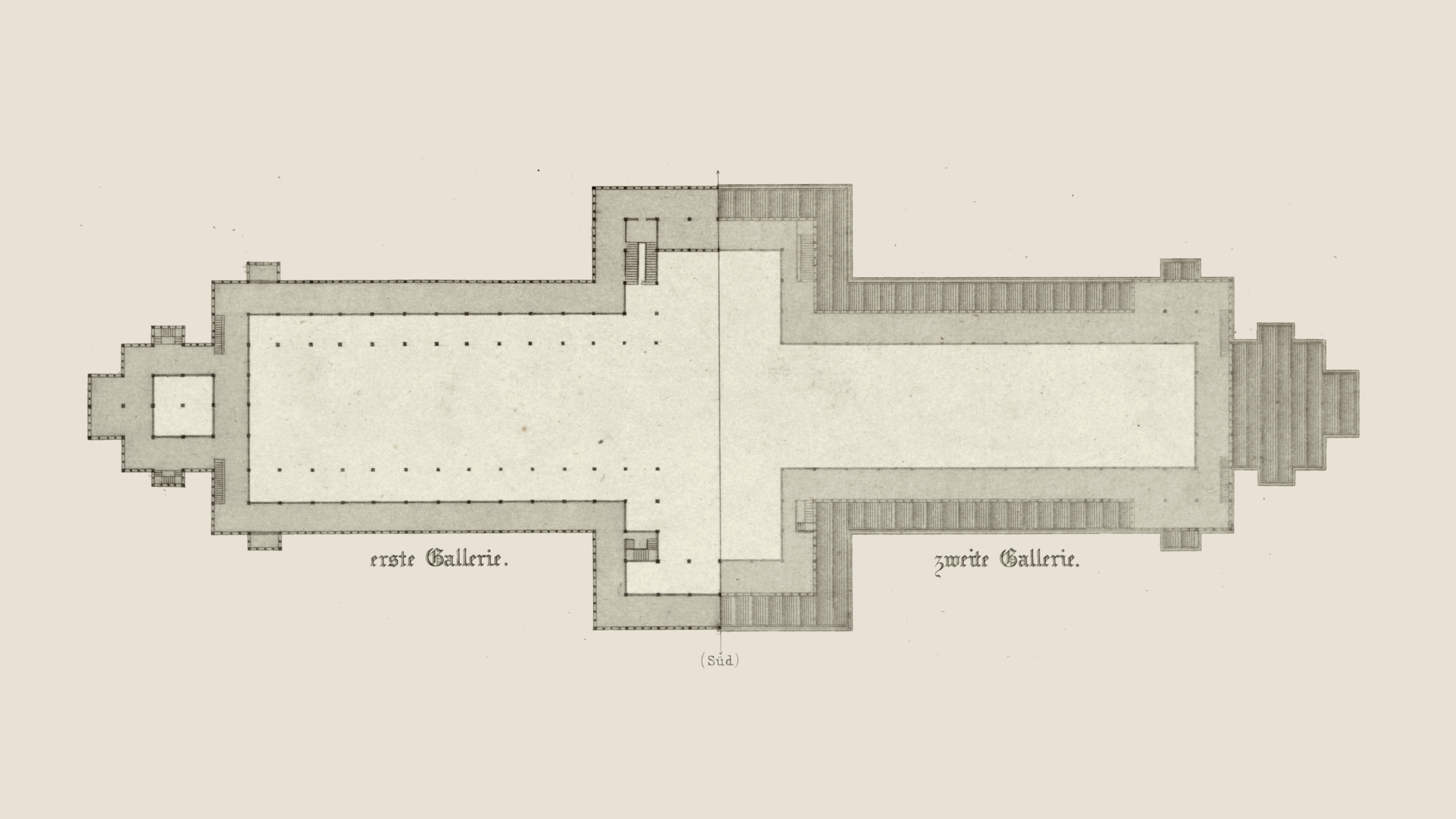
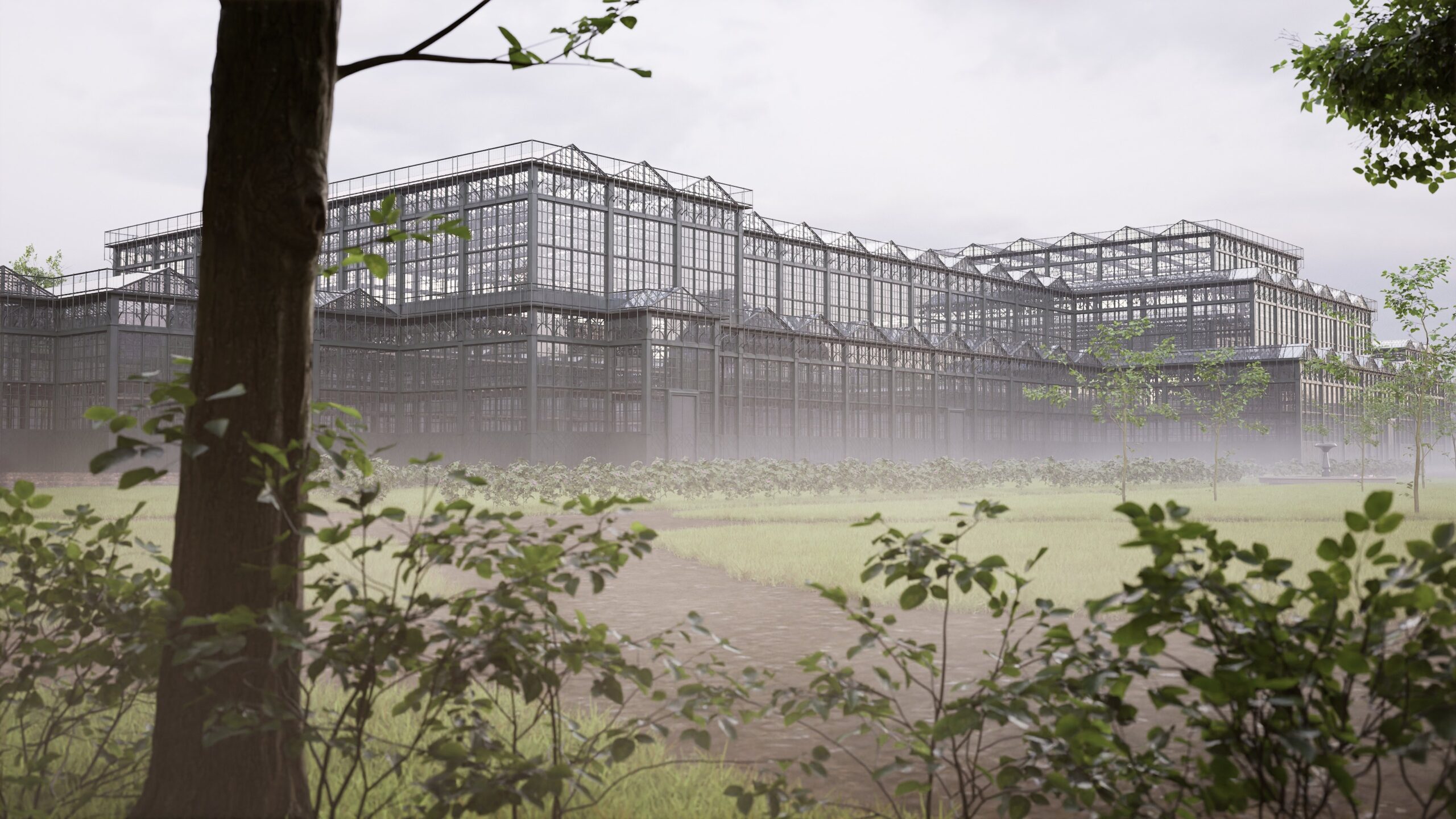
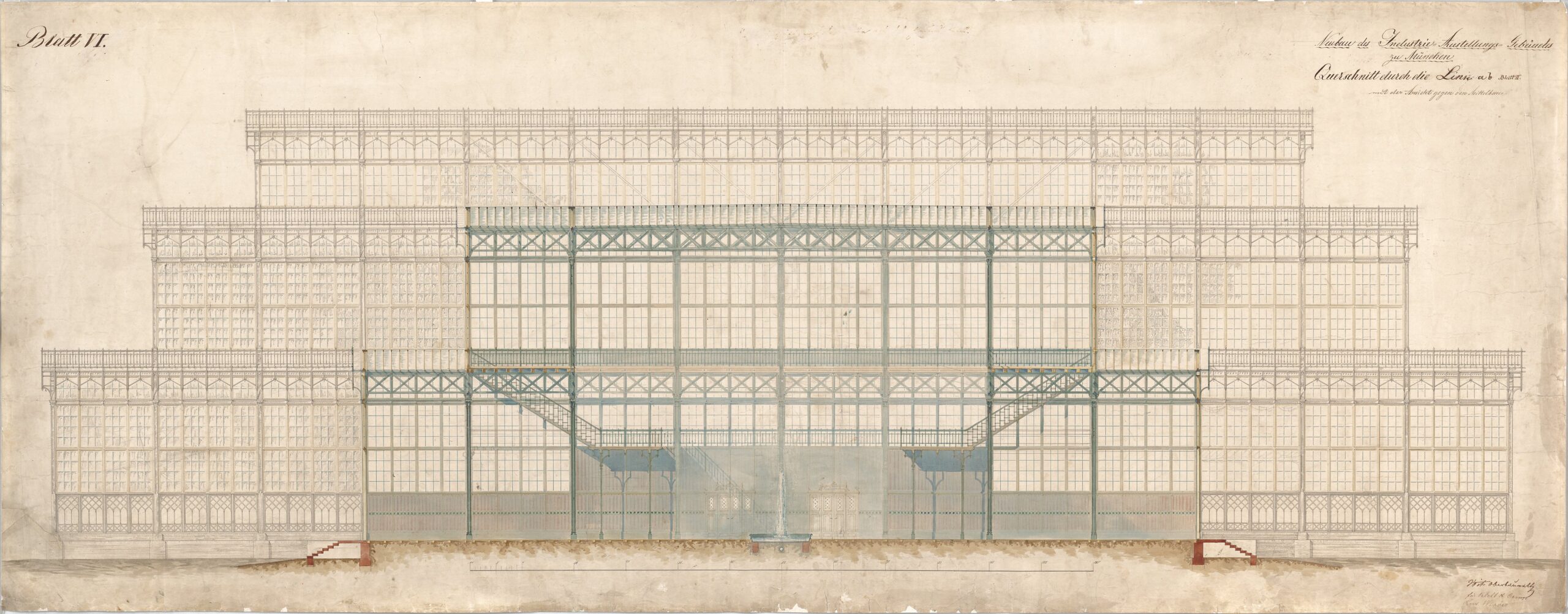
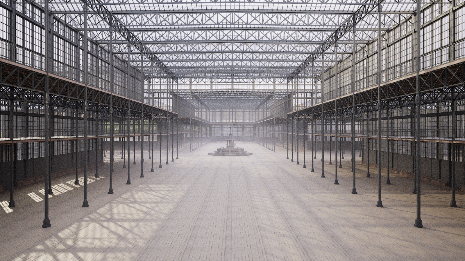
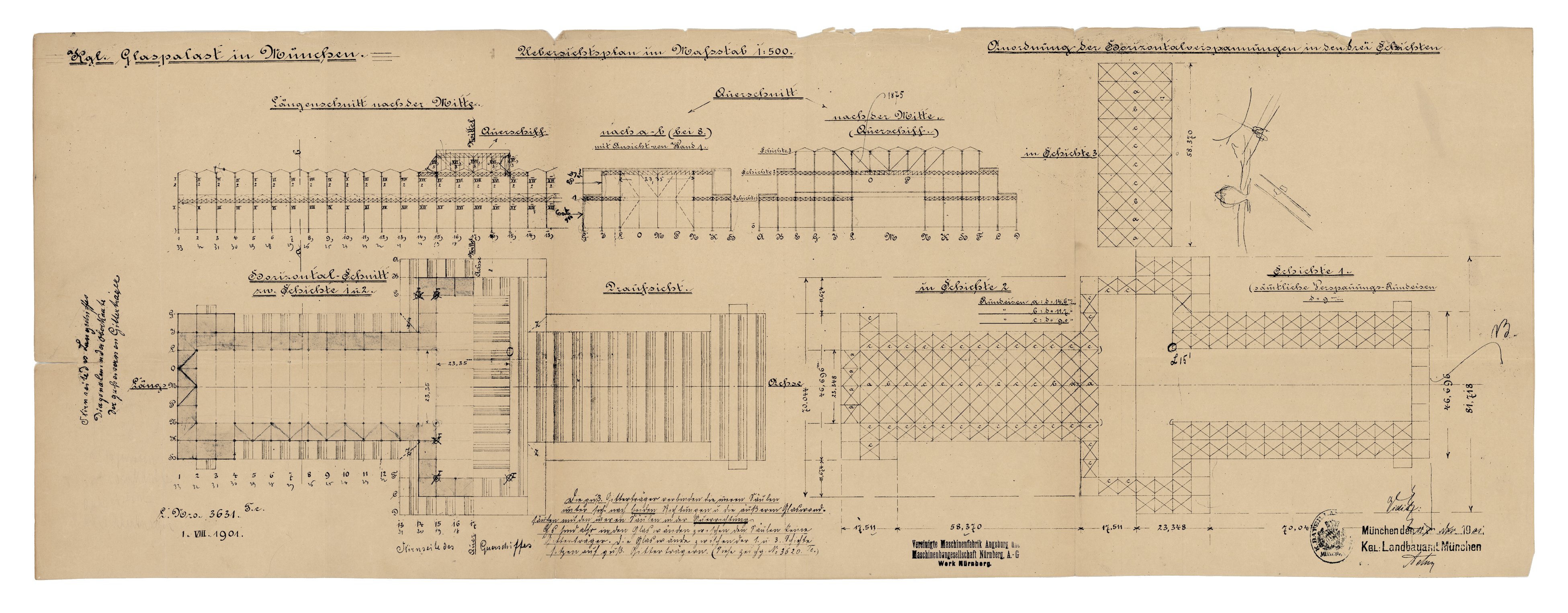
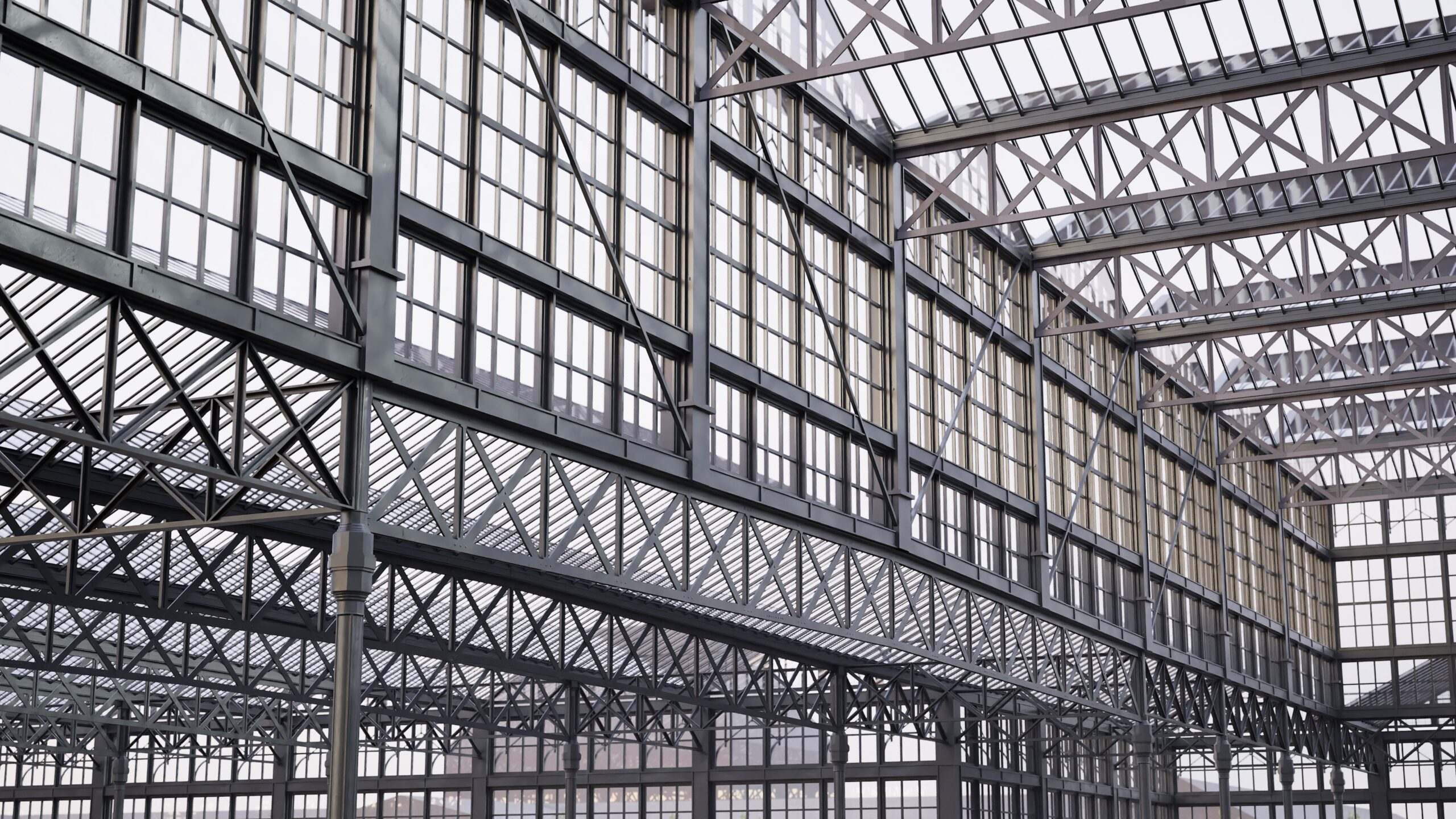
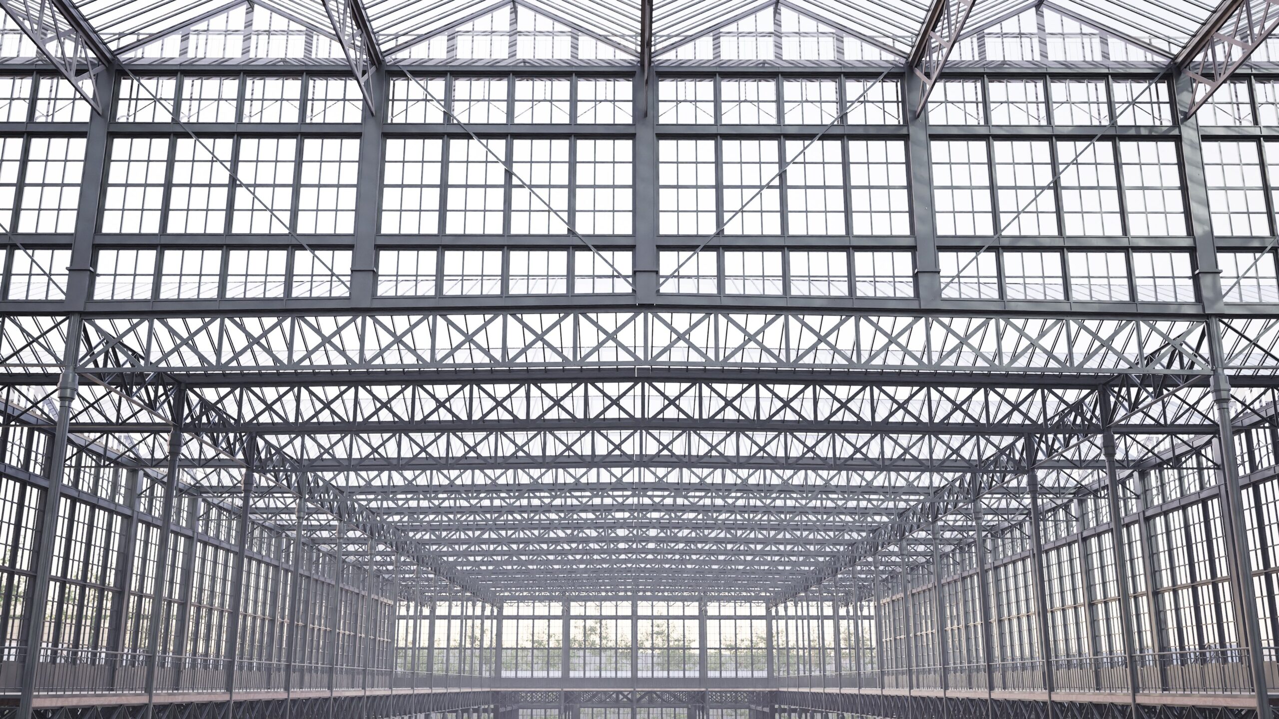
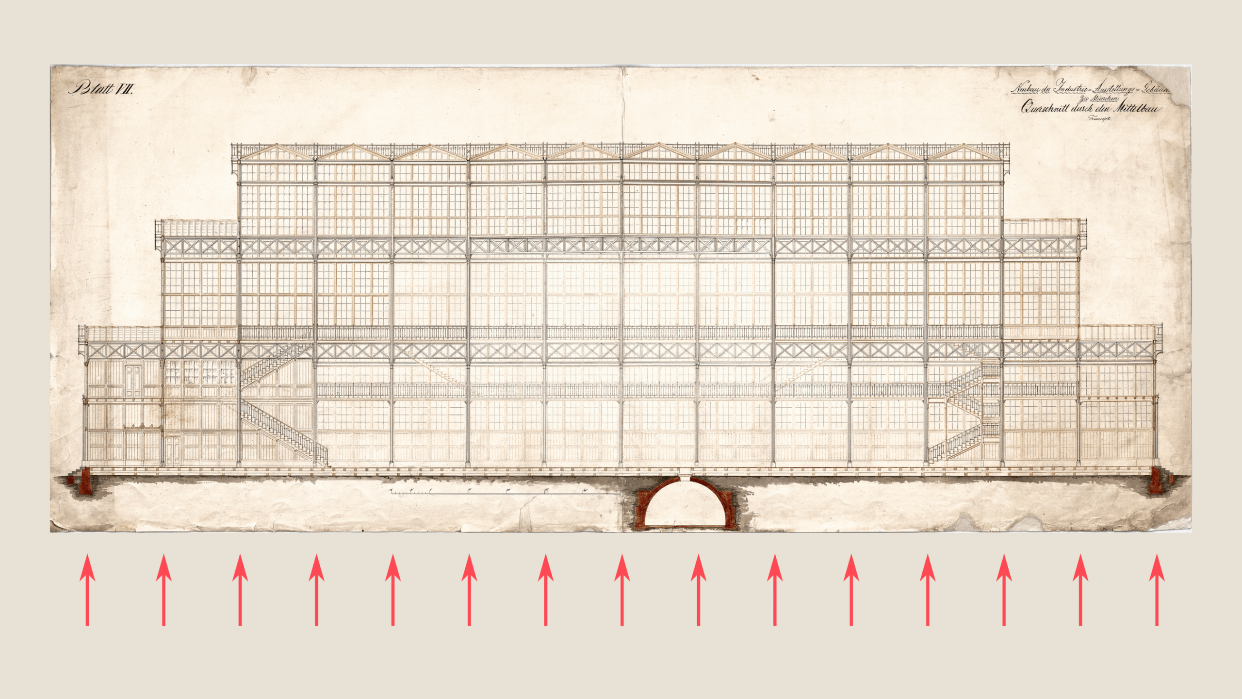
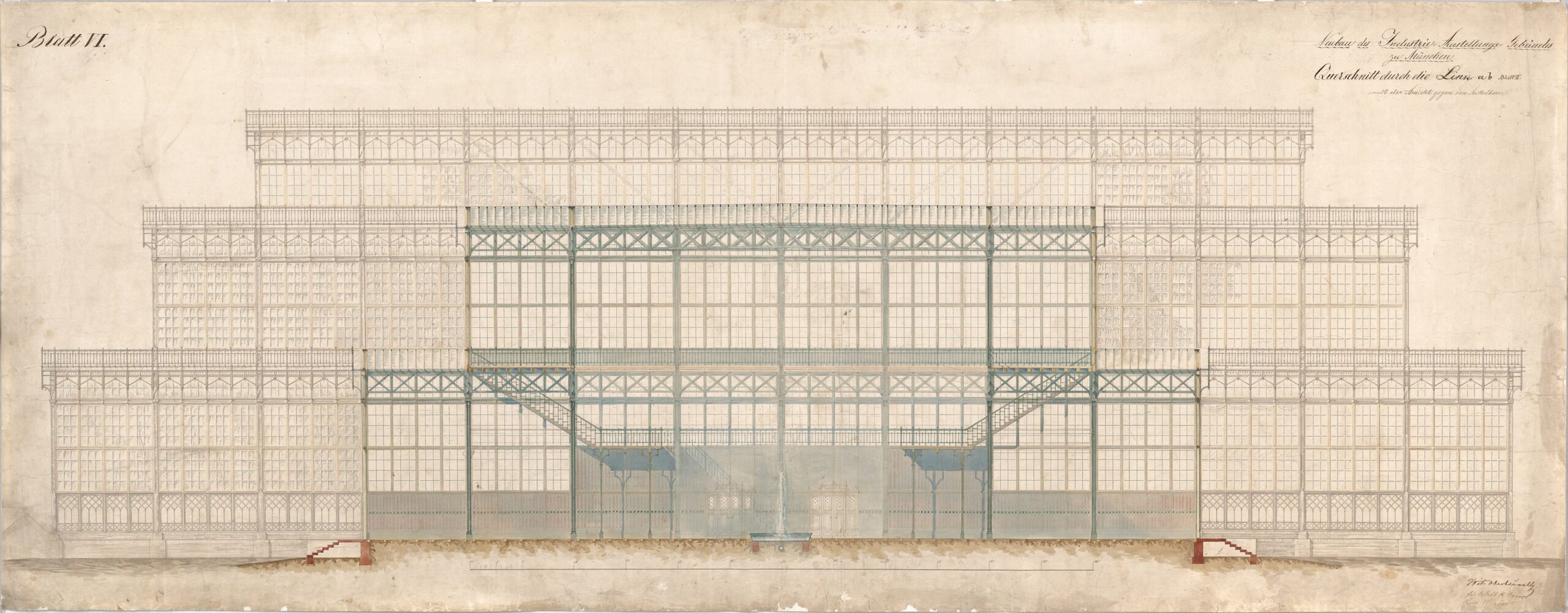
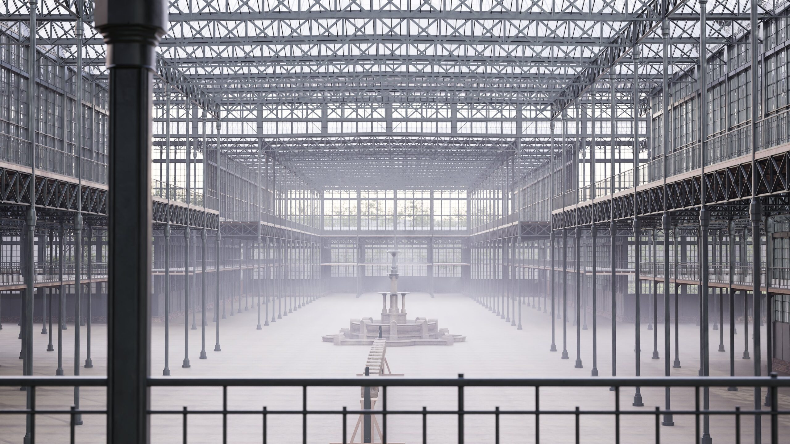
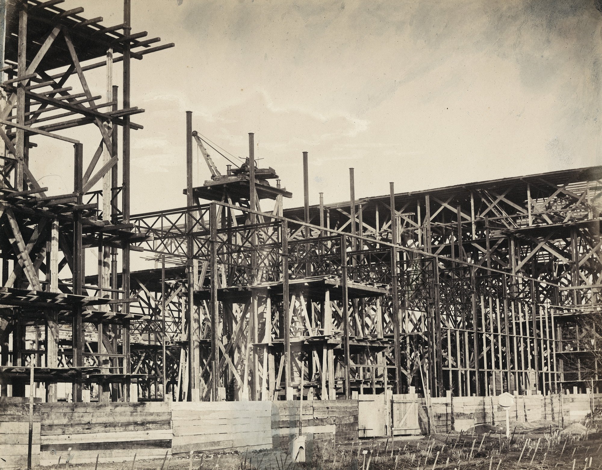
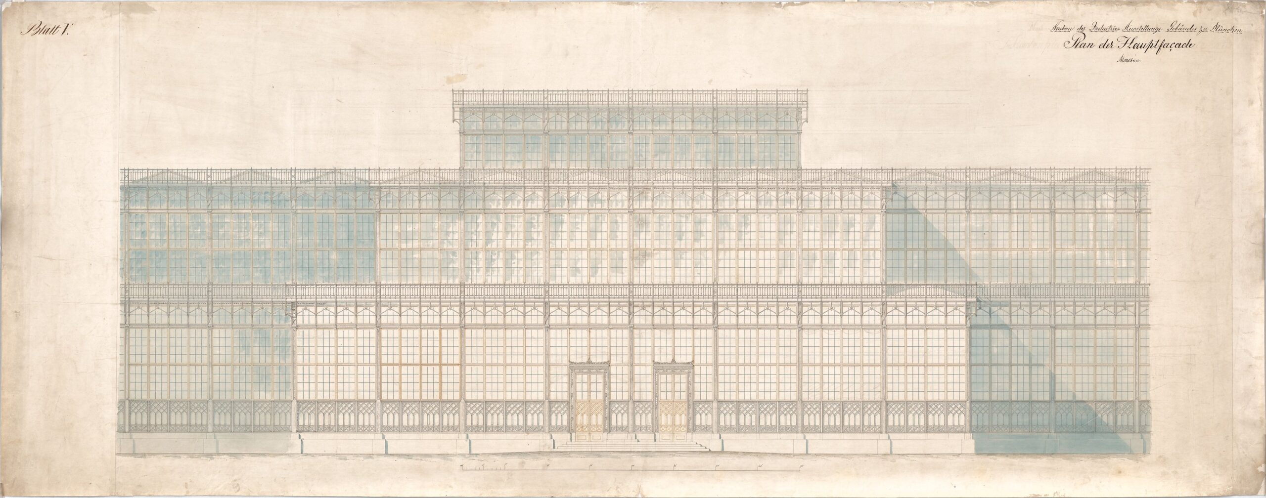
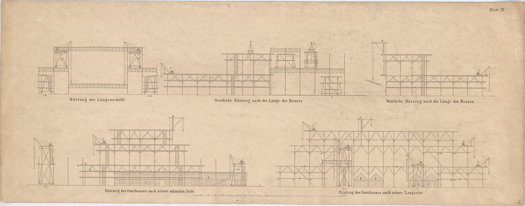
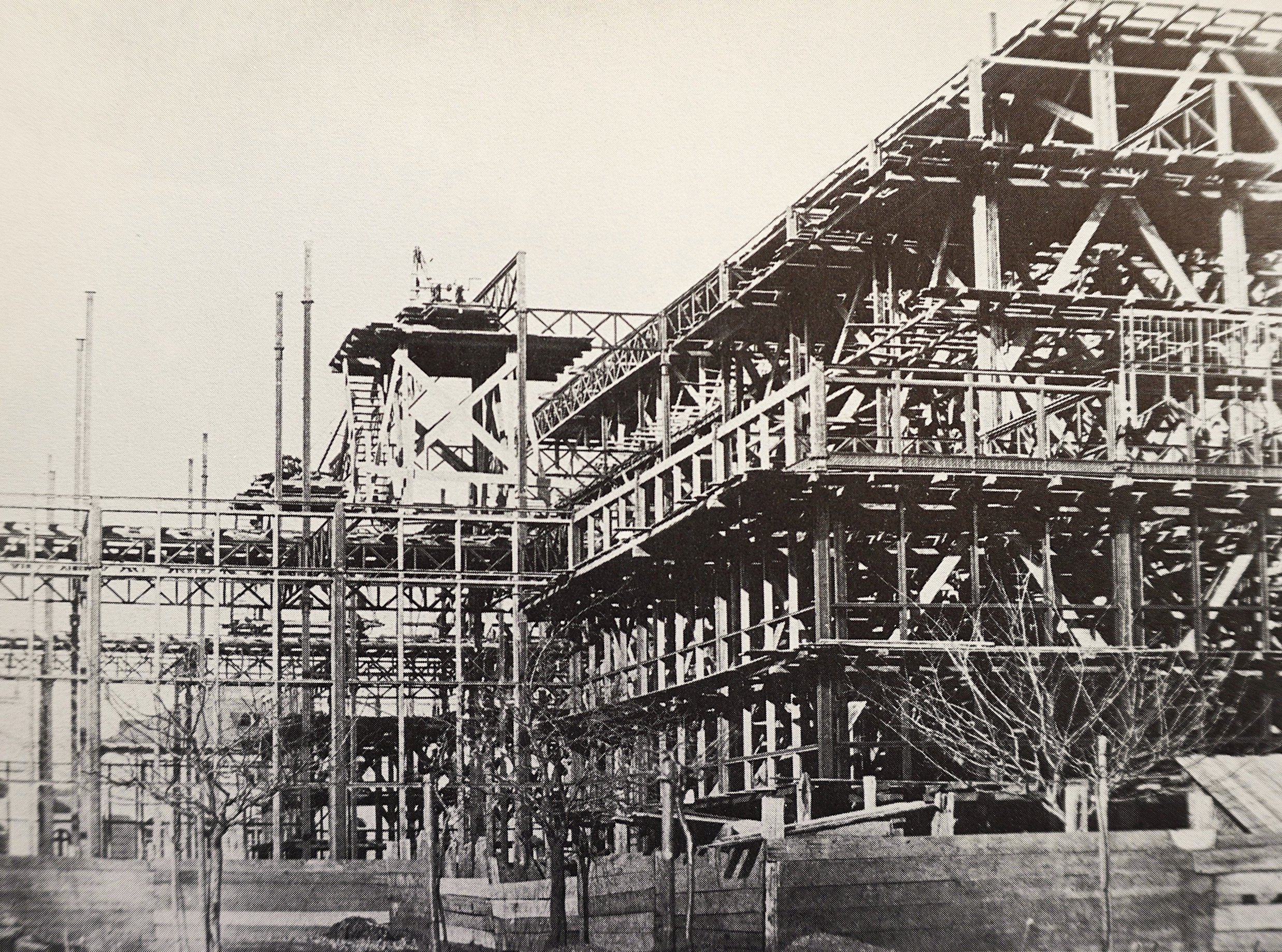
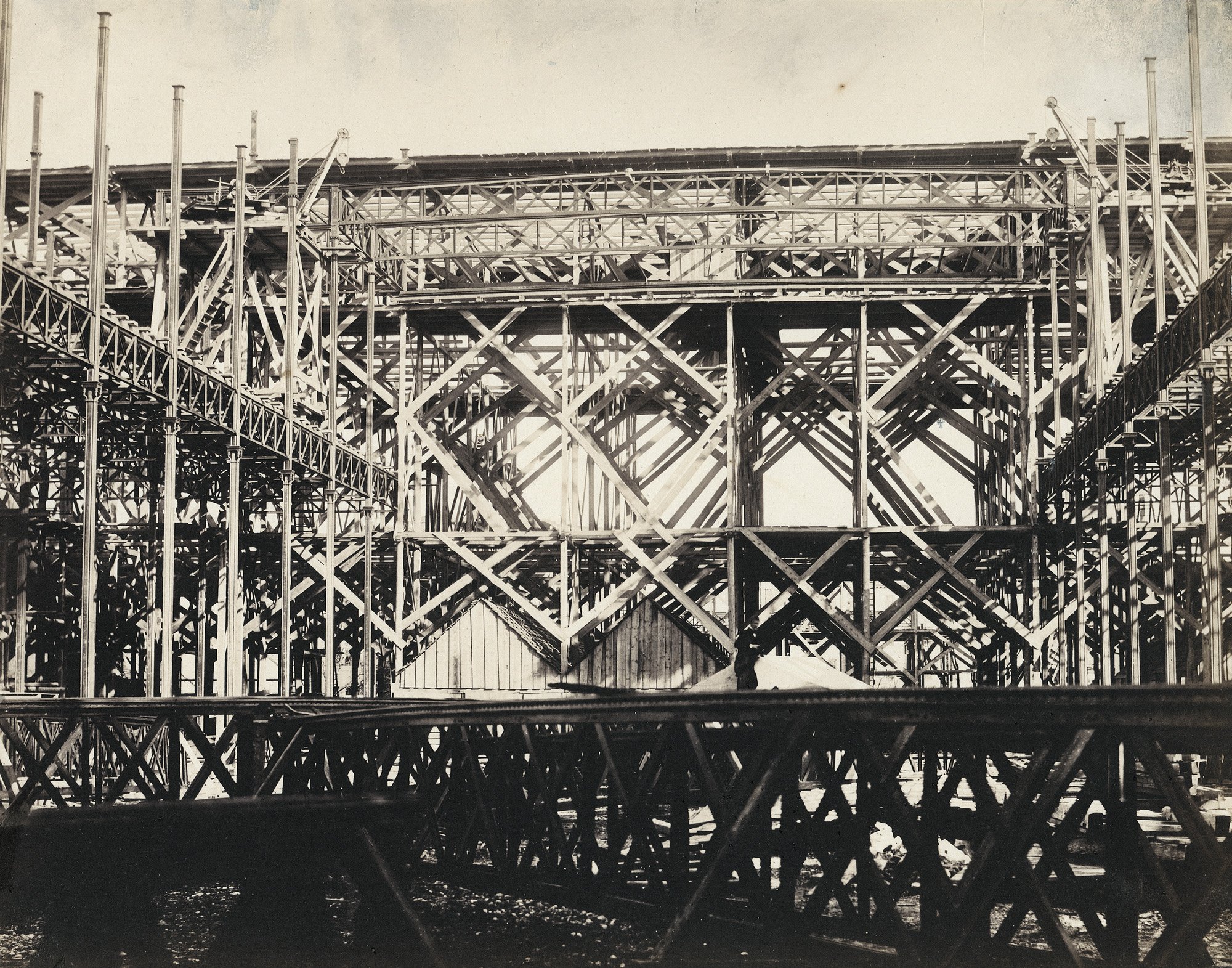
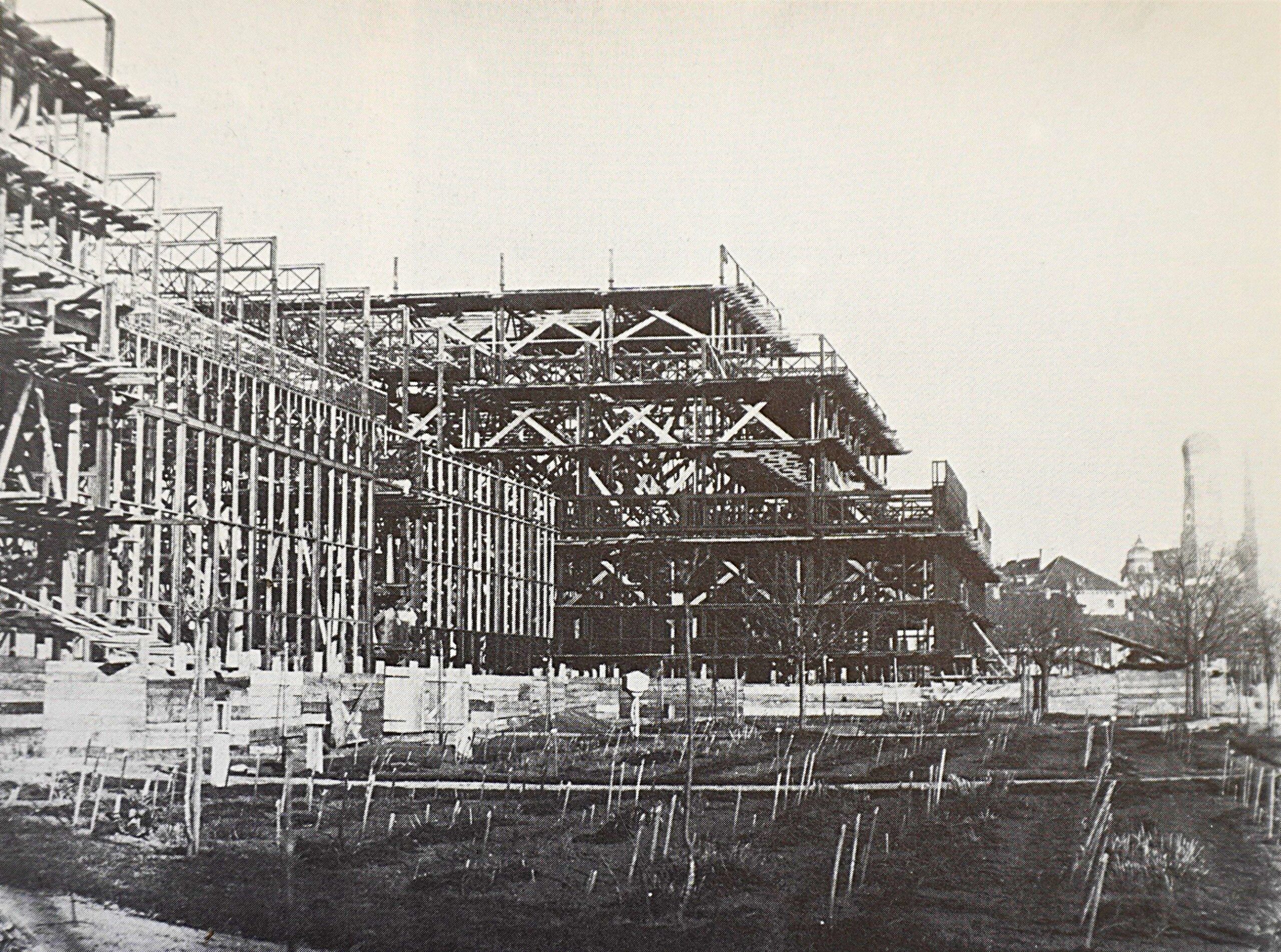
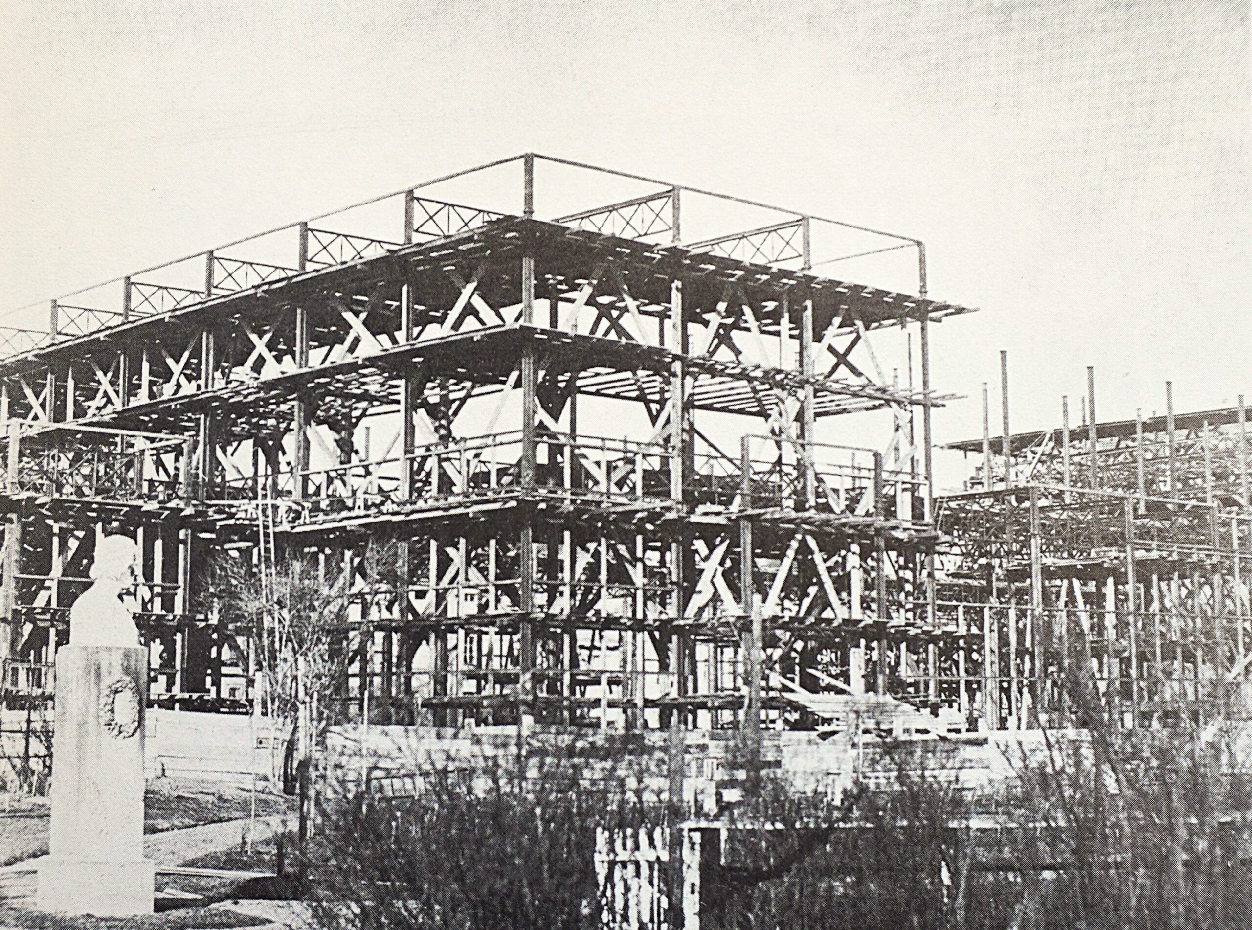
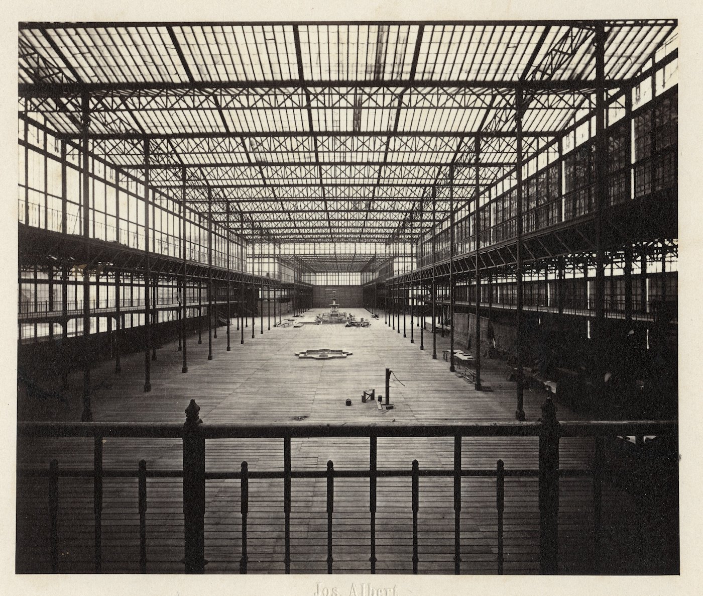
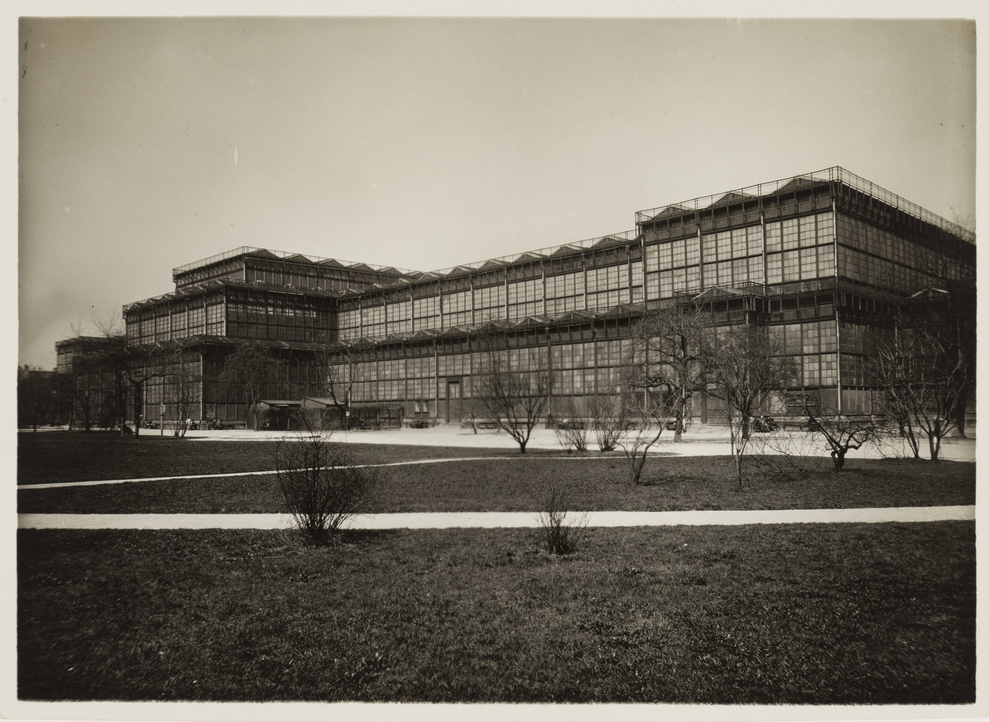
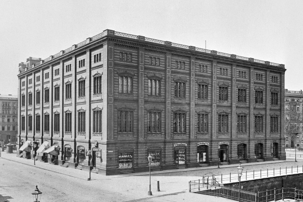
The Munich Glass Palace was built in 1854 as a prestigious royal project – a structure meant to make progress and cultural grandeur visible.

Although it was open to the public, not all groups had equal opportunities to exhibit there; for example, female artists were only marginally represented.

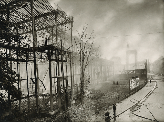
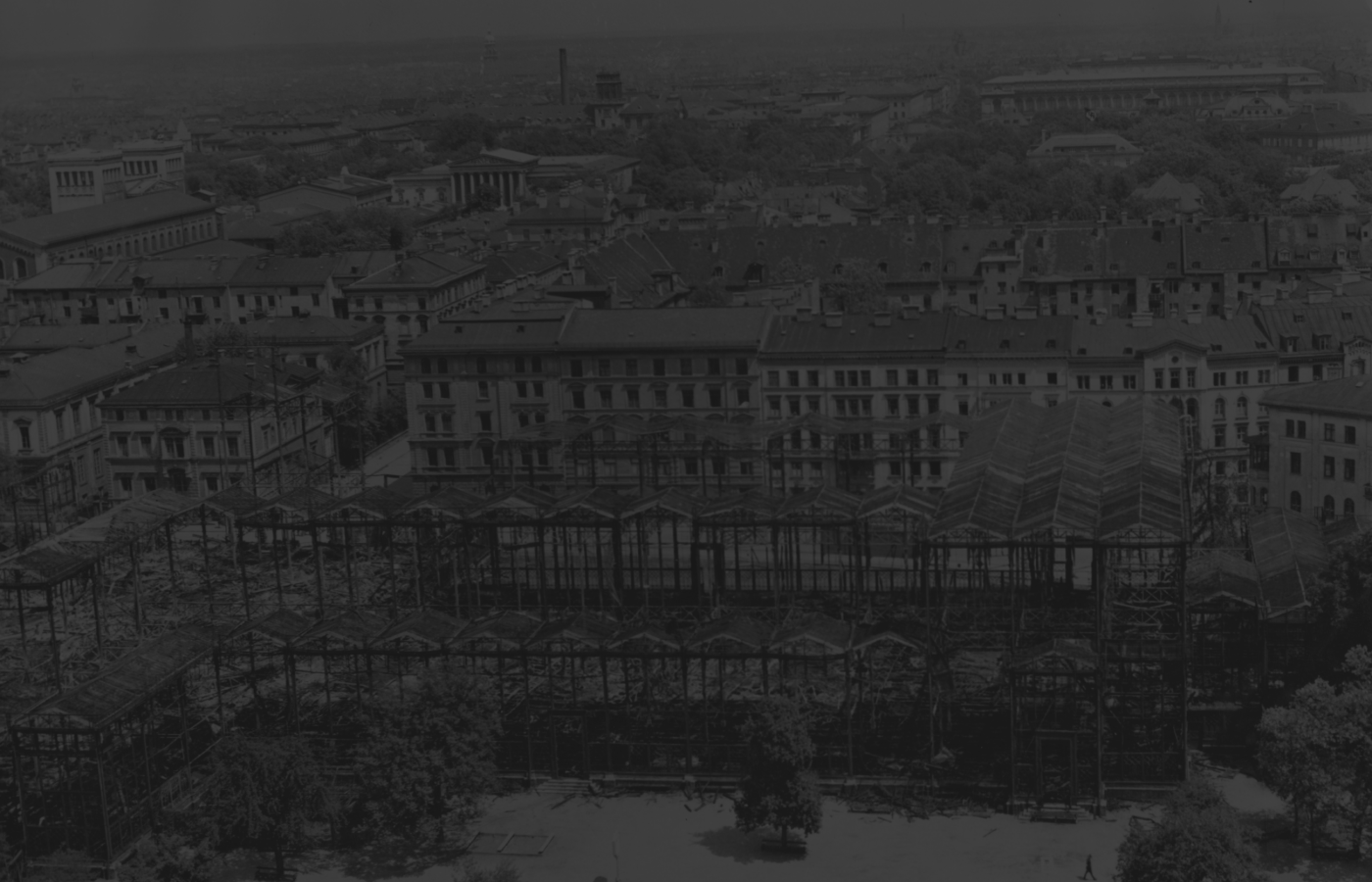
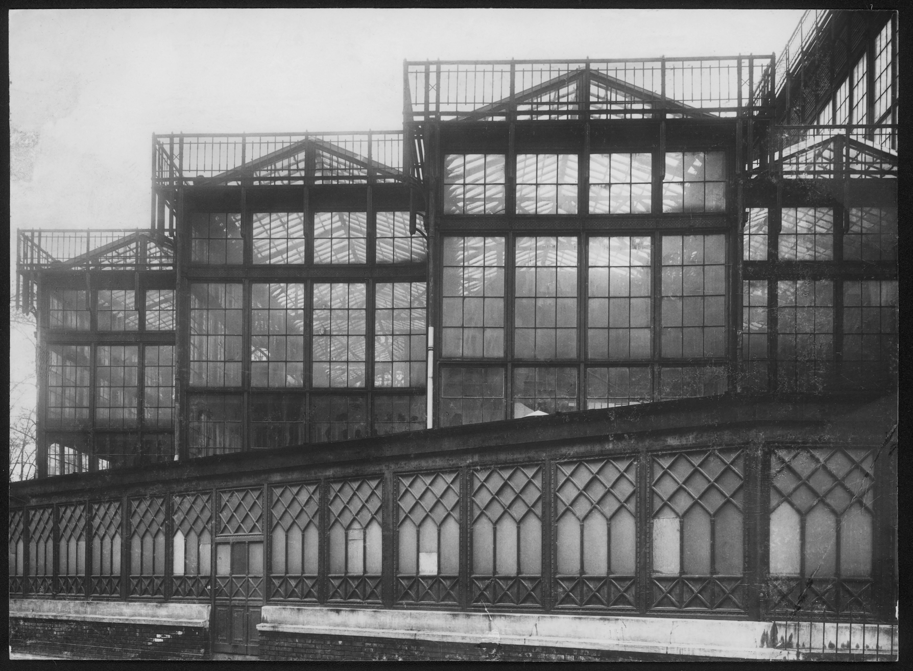
The Glass Palace stood until the devastating fire in the night of June 6, 1931. The exact cause of the blaze remains unclear — possibilities included spontaneous combustion, a technical defect, or arson. More than 3,000 artworks were lost, among them important works of German Romanticism.

Today, art and culture are regarded as democratic goods. Museums and exhibitions present themselves as open spaces, yet not all voices are heard equally.

The Glass Palace reminds us: the path from royal representation to democratic participation is a long one. The question remains as relevant as ever — who is visible in art and culture, and who remains unseen?

Let’s talk

Collaborate
with us

You have ideas for the content development of the museum and would like to exchange thoughts with us? We’d love to hear from you!

Collaborate as a Museum

Your museum is interested in a partnership? We offer a curated exhibition that we’d be happy to bring to your institution. Get in touch – we look forward to working together!

Become
a Partner

You’re passionate about structural engineering and believe in the importance of sharing it with others? We have big plans and are looking for committed partners. We’d love to hear from you!