NEW STRUCTURE RECOVERED: The Berlin "Bauakademie" has been online since April 20. Enjoy exploring it!

The

“Ahornblatt” 
Restaurant

The shell structures from the 1950s–90s are highly efficient, using double curvature to span large spaces with extremely thin concrete shells. Hand-calculated and economically built, they minimize materials, reduce CO₂, and are considered cutting-edge again today.

1969-1973

Four years of construction time for an architectural icon: The “Ahornblatt” is built in East Berlin as a visionary large restaurant with a futuristic shell construction.

7 Centimeter

The spectacular concrete shell, just 7 centimeters thick, is an ultra-light construction that combines stability and elegance. It consists of 5 almost identical individual shells and spans more than 2000 m² of floor space without supports.

941 kN

With a pre tension force of 941 kilonewtons, each shell is held together in the underground—equivalent to the force in a rope suspending 45 SUVs.

July 24th 2000

Despite protests, the “Ahornblatt” fell victim to the wrecking ball starting on July 24, 2000—an irretrievable loss for Berlin's architectural history and building culture in general.

The shell structures from the 1950s–90s are highly efficient, using double curvature to span large spaces with extremely thin concrete shells. Hand-calculated and economically built, they minimize materials, reduce CO₂, and are considered cutting-edge again today.

The Ahornblatt Restaurant

yr 1973 – 2000

  • Historical Background
  • History of use
  • Ownership History
  • Architectural Features
  • The “Ahornblatt” is an outstanding example of GDR modernism, also known as Socialist Modernism. At the end of the 1960s, architects Gerhard Lehmann and Rüdiger Pläthe began designing the building in collaboration with civil engineer Ulrich Müther. The project was commissioned by the GDR Council of Ministers. Construction began in 1969, and in 1973, the restaurant on Fischerinsel in Berlin opened its doors. It served as a self-service restaurant for employees of the surrounding businesses and offices, as well as for residents.
  • After its opening, the “Ahornblatt” is not only a restaurant but also functiones as a multi-purpose hall used for various events. In the 1990s, the building is repurposed as a nightclub called "Exit," which remaines in operation until 1994. Then followed by a six years of vacancy before the building is ultimately demolished, marking the end of its original purpose.
  • From 1973 to 1990, the “Ahornblatt” is owned by the GDR. After German reunification, ownership is transferred to the Federal Republic of Germany, which retains it until 1997. The building is then acquired by Objekt Marketing GmbH.
  • The “Ahornblatt” is particularly renowned for its distinctive roof structure. It consists of five hyperbolic paraboloid shells (hypar shells), each spanning 23 x 36 meters, complemented by a flat saddle roof extension that connects to an adjacent low-rise building. The Construction consists of reinforced concrete for the hypar shells and the foundation, prestressed concrete tension bands between the supports of the shells and a steel and glass façade. The roof is covered with folded aluminum sheeting. One of its most remarkable engineering achievements are the exceptionally thin reinforced concrete shells, measuring only 7 cm thick, which are stabilized by integrated edge chords. The entire roof rests on only 6 individual foundations in the low points of the hypar shell and a central support.
1-4

Dive into the structure of the “Ahornblatt” shell

Click on the feature buttons and discover original drawings, photos, videos and explanations that tell you a story about the Art of Engineering.

The construction
The hypar shell - geometry and load-bearing behaviour
Basic Principle of the “Ahornblatt” shell
Static Calculation of the “Ahornblatt” Shell
The shell – detailed
The edge chords and supports - detailed
The tension chord - detailed
The rib-reinforced cavity construction - detailed

The construction

The hypar shell - geometry and load-bearing behaviour

Basic Principle of the “Ahornblatt” shell

Static Calculation of the “Ahornblatt” Shell

The shell – detailed

The edge chords and supports - detailed

The tension chord - detailed

The rib-reinforced cavity construction - detailed

The construction

When constructing the shells of the “Ahornblatt”, the special features and advantages of the geometry development of the hypar shell are utilized.
The double-curved shape of a hypar shell can be developed from straight lines. This shape-forming principle was used to construct the timber formwork from straight squared timbers.
A scaffold made of tubular steel profiles served as the substructure for the timbers. The different height levels were adjusted using telescopic supports.
The squared timbers were planked with straight boards. This created a closed surface on which the concrete could be poured.
Each formwork segment rests on only 3 individual foundations. Once the foundations have been completed, the five roof shells were manufactured one after the other and individually. The work began with the centre shell. This original plan also shows the additional support of the edge chords on the long sides during construction phase.
Once the steel reinforcement had been laid in the timber formwork, the concreting work could begin on the surfaces, some of which were very steeply inclined. The concreting method used for this was particularly noteworthy: the shotcrete method.
In this process, the concrete is pneumatically conveyed through a hose to the installation site and sprayed at high pressure through a nozzle. The impact energy automatically compacts the material upon contact with the surface. This technique makes it possible to concrete the complexly shaped shells of the structure with steep inclines precisely and efficiently.
Old Super 8 footage shows excerpts from the construction of the “Ahornblatt”.
1/7

The hypar shell - geometry and load-bearing behaviour

A hypar shell is a double-curved surface. One way of developing the geometry utilises the fact that the hypar surface can be formed from straight lines. This shape development willl here be described in detail.
Step 1: Determine the base of the hyperbolic surface using four corner points. These points must be defined in such a way that they form a rhombus.
Step 2:
The boundary lines of the rhombus are divided into equal segments
Step 3:
The segment ends form the starting points of the straight lines that connect the opposite edge lines. They all lie on a flat surface - the base surface.
Step 4:
A hyperbolic surface contains two opposite high and two opposite low points. The high points are created by vertically moving two corner points from the base. Here: A’ to A and C’ to C.
Step 5:
The base is now pulled "upward" at the corners A' and C' to form the high points A and C. As a result, points B and D become the low points. The edge lines remain straight, as do all lines in the surface.
The lines distributed in space along the base remain straight but now span a double curved surface in space. This surface is called a hyperbolic paraboloid.
Within this area, parabolas can be seen. There are parabolas that open upwards and parabolas that open downwards.
They show the second way in which a hypersurface can be constructed, namely by moving the parabolas that are open upwards (blue) along the parabola that is open downwards (red) or vice versa.
The load-bearing system of hypar shells is not based on straight lines, but on parabolas. The parabolas that are open at the bottom act as compression arches and the parabolas that are open at the top act as tension arches. These arcs transfer the loads of the shell to the edges via tensile and compressive forces.
The edge chords absorb the loads from the roof surface and transfer them to the individual foundations at the low points of the hypar shell.
1/7

Basic Principle of the “Ahornblatt” shell

The distinctive roof of the “Ahornblatt” consists of five hypar shells, arranged in the shape of a stylized maple leaf.
Each of these shells is a segment of a hyperbolic paraboloid (hypar shell) – a doubly curved surface that curves in two opposite directions, creating the characteristic saddle shape. This shape is formed by a specific arrangement of straight lines in space.
In plan view, the area spanned by each shell is a diamond shape with axis lengths of approximately 23 × 36 meters. Each individual shell thus spans an area of over 400 m². The construction of each shell can be divided into four sections:
a) the load-bearing thin shell, b) the reinforcing edge chords surrounding the shell, c) the foundations under the low points and d) a cavity construction, providing additional stability.
Under load, intersecting parabolic tension and compression curves form in the shell, carrying the external loads. Shear forces develop along the edge chords between the shell and the chords, which are absorbed by the chords and transmitted to the supports through downward-increasing compression.
The edge chords transfer the forces to the supports. From there, the forces can be divided into a horizontal and a vertical component.
The vertical component of the forces is transferred into the ground through piles.
The horizontal component is neutralized by a pre-stressed tension chord installed in the underground.
This original excerpt from Ullrich Müther's calculations shows the loads acting on the foundations and the corresponding prestressing force in the tension chord. The loads are given in the non-SI-compliant unit "pond," as was customary at the time.
At the rear of the shell, there is a flat hollow box. This is unusual for shell structures, but necessary due to the lack of stiffness in the rear shell area. The structural shell effect is hardly present there, as the shell is very flat and has only slight curvatures.
In this area, an additional support column is installed, which servs as a vertical support for all five shell sections of the “Ahornblatt”. The single column creates large bending moments in the shell surface, which can only be absorbed in the less curved shell by increasing the shell thickness, here in the form of a flat ribbed box girder.
1/7

Static Calculation of the
“Ahornblatt” Shell

The basic concept of the shell structure of the “Ahornblatt” is based on the idealized geometric principle of the hypar shell.
If the required geometric conditions for a hypar shell are fulfilled, the membrane theory can be used for the static calculation of the shell. This theory provides formulas for calculating the forces and stresses in the shell.
However, the mentioned formulas are only valid as long as the shell remains free of deformation. This is initially assumed as an approximation for large areas of the “Ahornblatt”. For the „Ahornblatt“, the following values are obtained for the principle compressive and tensile forces.
However, this theoretical shape does not exactly correspond to the actual planned shape of the “Ahornblatt” shell. The shell is only a segment of an ideal hypar shell. In reality, the edges bend slightly at the long sides. As a result, the desired geometric shell effect cannot fully develop. Therefore, the results of the calculations based on membrane theory do not provide accurate values for the “Ahornblatt”. Therefore, further investigations are necessary.
The forces in the shell could be significantly greater locally than calculated by using membrane theory. It is no longer guaranteed that no undesirable deformations would occur. Therefore, the reviewing engineer at the time required that, in addition to membrane theory, the beam analogy and a model statics analysis shall also be carried out to determine the forces in the shell. The key values from the three static methods would then be used for the final design. These analyses revealed some weaknesses in the original concept.
In the method of beam analogy, the shell was reduced to a simple, statically determined beam with a cantilever. To achieve this, the shell was divided into strips. The weight of each strip, as well as the roof load acting on it, were considered as multiple point loads on the beam according to the strip division. In this way, the vertical load acting on the foundations could be determined.
The model statics analysis provided the crucial values for the final roof geometry. For this purpose, a true-to-scale model was built and loaded at the time. At the same time, stress measurements were carried out directly on the model.
The stress values determined on the model were converted to the real scale using scaling factors so that they reflected the load-bearing behaviour and the actual forces in the structure.
The results of the model statics analysis have shown that the stresses in the rear, very flat area of the shell are too high to be taken up by the 7 cm thin shell. Further tests with model statics were conducted in order to optimize this area. A rib reinforced cavity structure ensured sufficient load-bearing capacity and rigidity. This raises the fundamental question today: Can the “Ahornblatt” be considered a pure hypar shell? (2/2)
1/7

The shell – detailed

This original plan shows how the reinforcement mats of the bottom layer are to be laid in the shell. The direction of the reinforcement mats corresponds well with the principle compressive forces.
Another original plan shows the laying of the so-called reinforcement of the trajectories. This reinforcement absorbs the tensile forces from the tensile parabolas of the shell and transfers them to the edge chords.
This original photo from the construction period shows how the reinforcement of the trajectories is laid around the high point. To prevent the reinforcing bars from slipping due to the large inclination, they were temporarily anchored behind the edge formwork.
This section of the virtual 3D model shows the bottom layer of the reinforcement mesh.
Another section of the virtual 3D model shows the reinforcement of the trajectories.
1/7

The edge chords and supports - detailed

Here we can see how important the edge chords of the shell are. This sequence was recorded during the demolition. As soon as the pliers cut through the edge chord, the entire shell collapses.
This original plan shows the required and installed longitudinal reinforcement of the edge chords. The edge chords absorb the shear forces from the shell and transfer them to the supports. This generates large forces that can only be absorbed by sufficient steel reinforcement.
This section of the virtual 3D model shows the edge chord reinforcement in the area of the high point.
This original plan shows the geometry of the support of the shell and the steel insert for transferring the shear forces into the foundation.
Another section of the virtual 3D model shows the edge chord reinforcement around the low point. Here it is welded to the steel insert to correctly transfer the shear loads of the shell to the supports.
This original drawing schematically shows a support of the shell. Another welded steel component consisting of I-profiles ensures that the forces from the horizontal shear of the shell are transferred to the plane where the tension chords are located.
This section of the virtual 3D model illustrates this steel component.
1/7

The tension chord - detailed

This overview plan shows the pre-tensioned tension chords under the five shells. The tension chords connect the individual supports of the shells and, with their high tensile forces, prevent the supports from sliding outwards
An original plan shows the reinforcement and the tendons in the tension chord. Two tendons apply a prestressing force of 941 kilonewton to the tension chord, thereby compensating for the horizontal shear of the shell supports.
An original photo shows the tension chord. After completion of all the shells, this will be filled with soil and will later lie at the level of the floor slab.
Another original photo shows the two anchors with which the prestressing force was held in the prestressing tendons.
This extract from the virtual 3D model showing the tension chord.
Another extract from the virtual 3D model shows the tendons in the tension chord
1/7

The rib-reinforced cavity
construction - detailed

The model statics analyses have shown that a rib-reinforced cavity construction is required in the rear area of each shell to give the supporting structure sufficient stiffness. This original plan shows the geometry of the cavity construction.
This section from the virtual 3D model shows the arrangement of the cavity construction. In the longitudinal direction, it consists of the two edge chords and a center rib. Two transverse ribs are provided for stiffening in the transverse direction.
This original plan shows the reinforcement within a transverse rib. The mesh reinforcement of the 7 cm thin shell can also be found here.
Another original plan shows how the center longitudinal rib was reinforced. The longitudinal reinforcement must be anchored in the column using connecting reinforcement. The same applies to the longitudinal reinforcement of the edge chords.
An original reinforcement plan of the column shows the highly reinforced column. This column serves as a support for the vertical forces from the five shells.
This snippet from the virtual 3D model illustrates the support situation in the rear area of the shell.
1/7

Explore the structure of the "Ahornblatt" Restaurant in the comfort of your home.

Here you can download the entire VR exhibition of the "Ahornblatt" restaurant for free.

Pause

Who made this
project possible

Funding

Click here to access the complete image credits.

Where were the lost structures located? Find them on the map.

Berlin

The “Ahornblatt” Restaurant

This double-curved concrete shell structure enables large spans with minimal material use. Its futuristic form shapes the Berlin cityscape beyond the GDR era.

Berlin

The Berlin “Bauakademie”

This masonry skeleton construction is a prototype building with a uniform column grid, consisting of rib-reinforced vaulted ceilings, masonry columns , and arches, which set standards for economical and functional construction throughout Prussia.

Berlin

The “Anhalter” Train Station

This masonry structure with pin-jointed iron truss arches connects Berlin to the world. A train station whose innovative roof structure, at the time, featured the largest span in Europe.

Berlin

The Old “Kaisersteg”

This iron truss bridge with an arch and central hinge connects two districts of Berlin. With a main span of 86 meters, it was a technical masterpiece of its time and represents innovative bridge engineering of the late 19th century.

Schmehausen

The Cable Net Cooling Tower

The cable-net cooling tower of the Hamm-Uentrop nuclear power plant in Schmehausen is globally unique in its design. The load-bearing network of steel cables replaces traditional concrete structures, enabling an exceptionally lightweight and efficient construction.

Munich

The Munich Glass Palace

This cast steel and glass structure is built in 1854 using innovative industrial manufacturing processes in a very short time. Although intended as a temporary building, it shaped Munich’s reputation as a city of art for over 75 years through its exhibitions.

Weimar

The Hetzer Timber Halls

The timber halls of the company Otto Hetzer AG were based on a construction principle patented in 1906: glued and curved timber elements that enabled large spans – a groundbreaking innovation in timber construction.

Awareness information

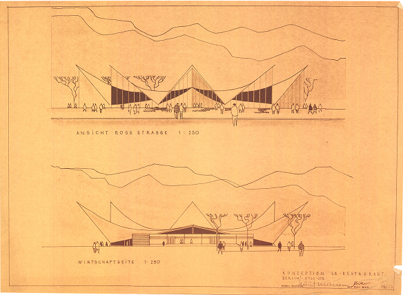
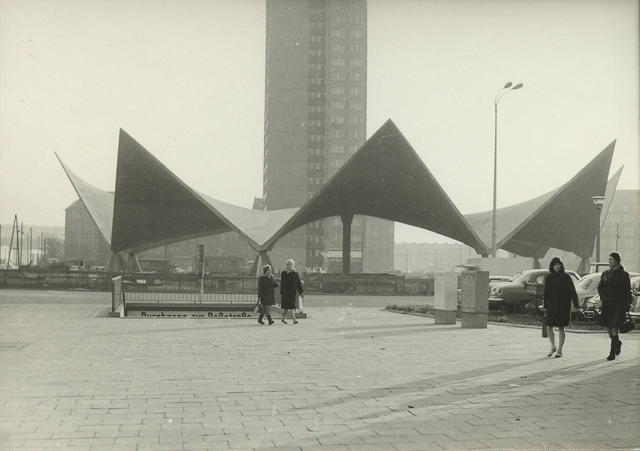
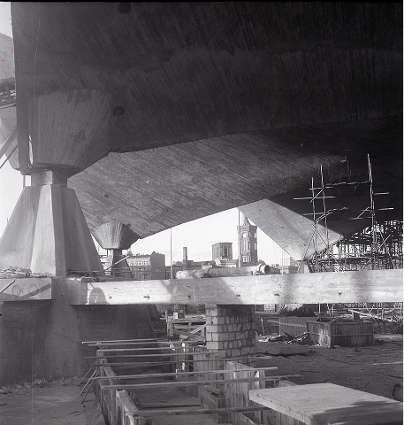
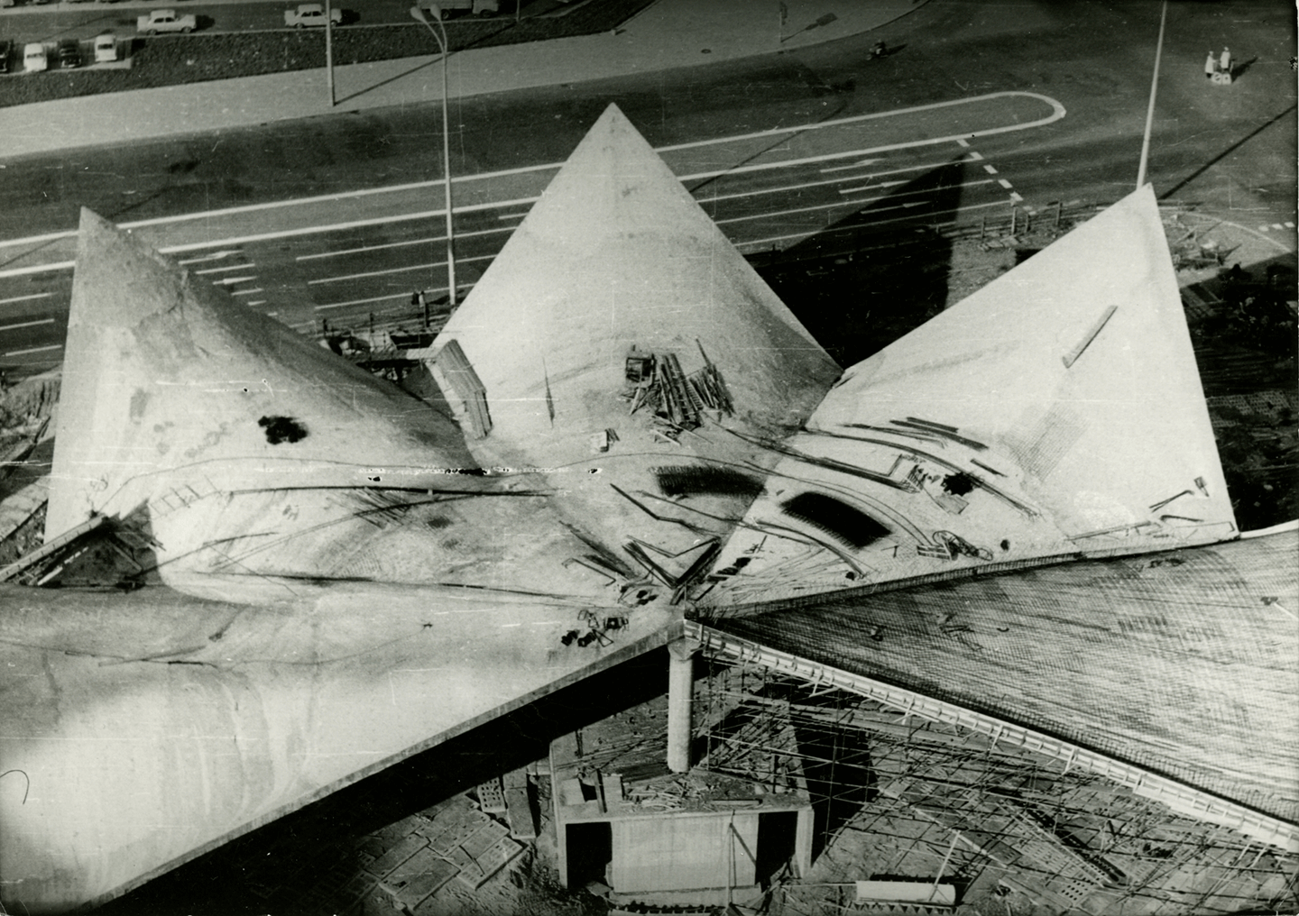
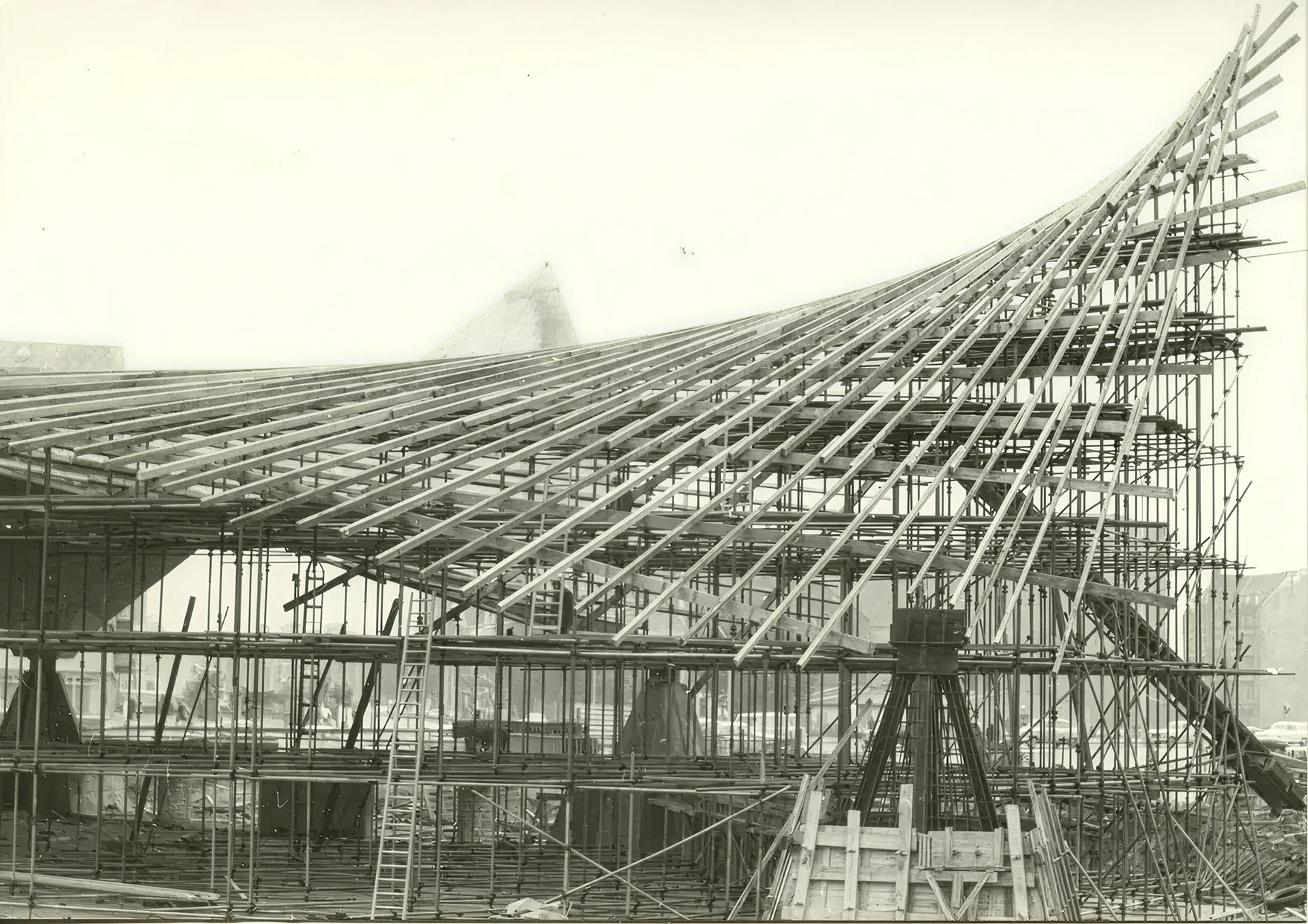
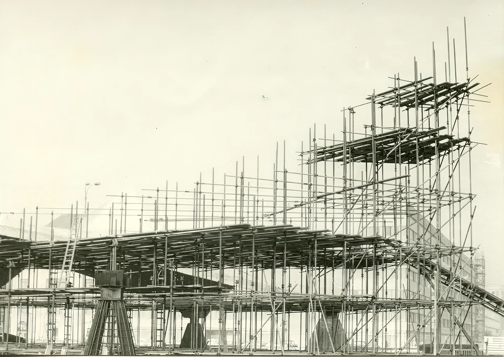
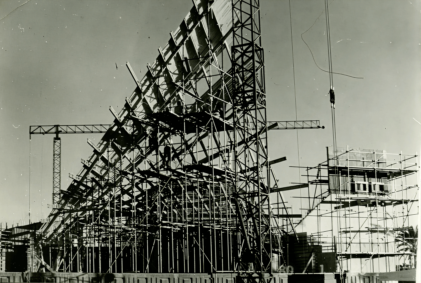
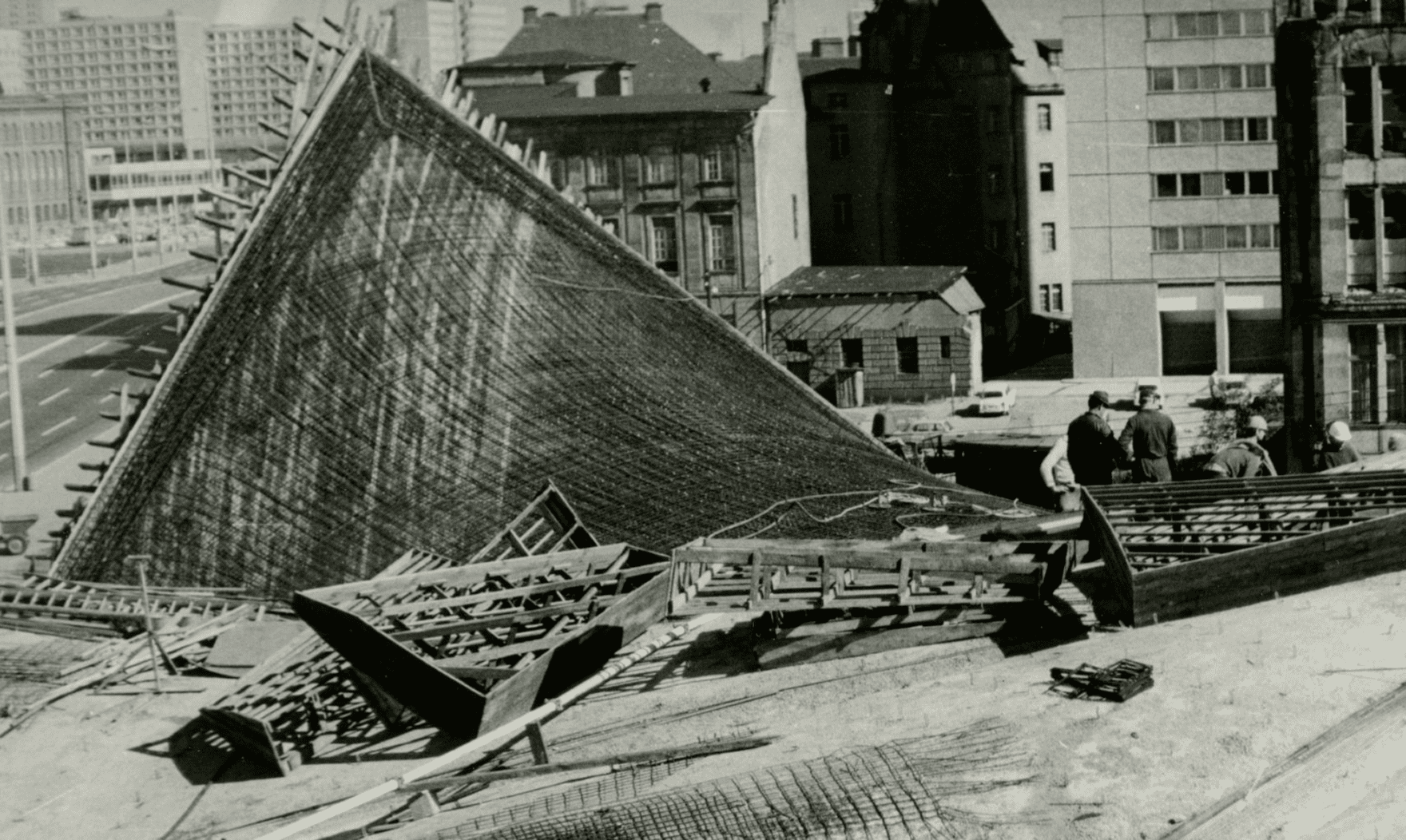
The Ahornblatt restaurant:

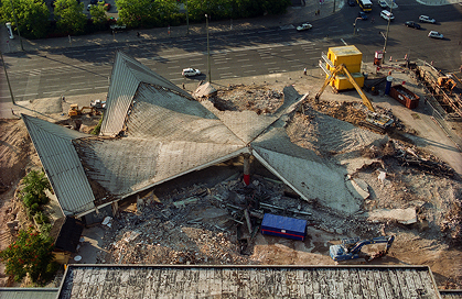
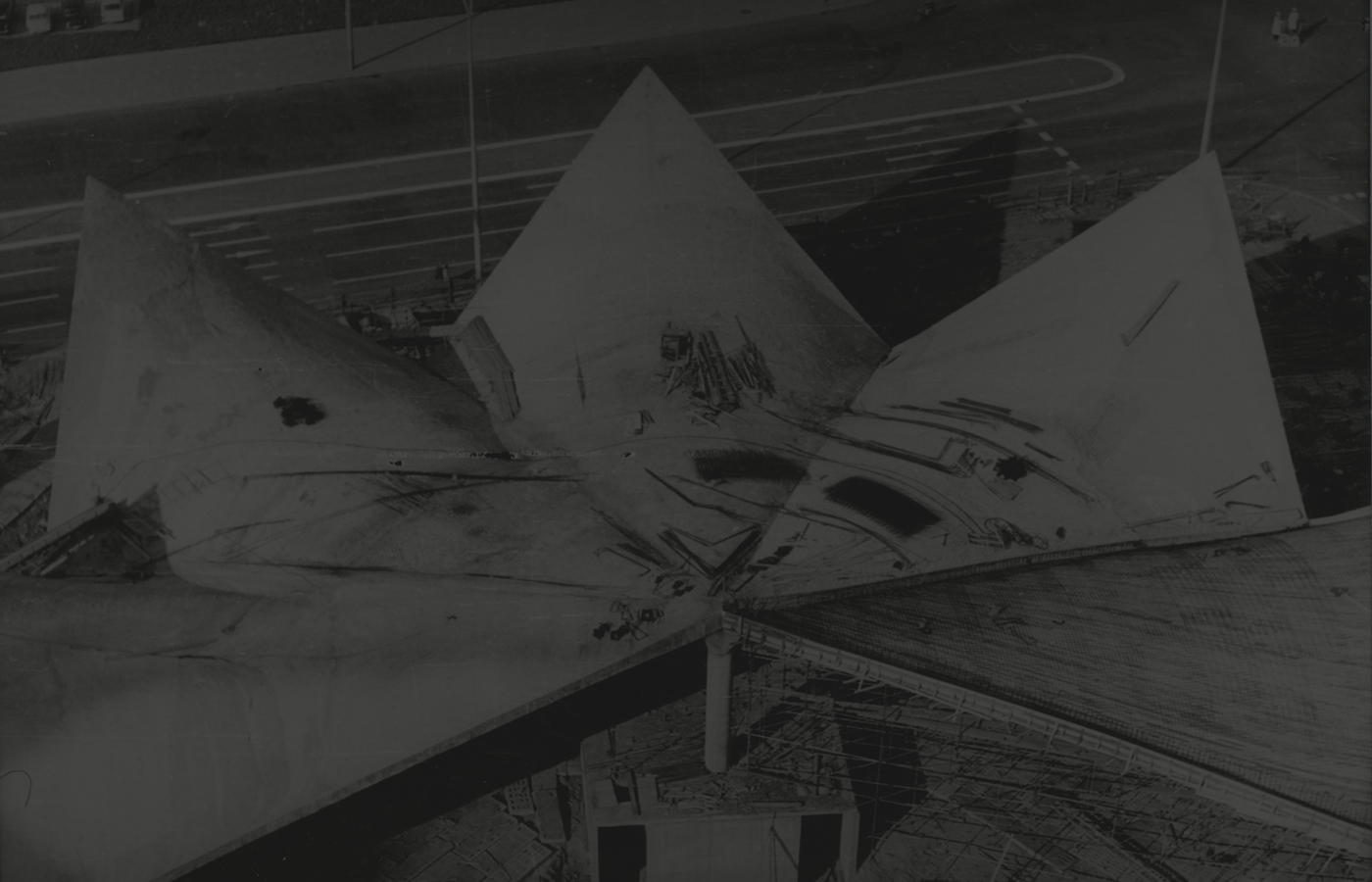
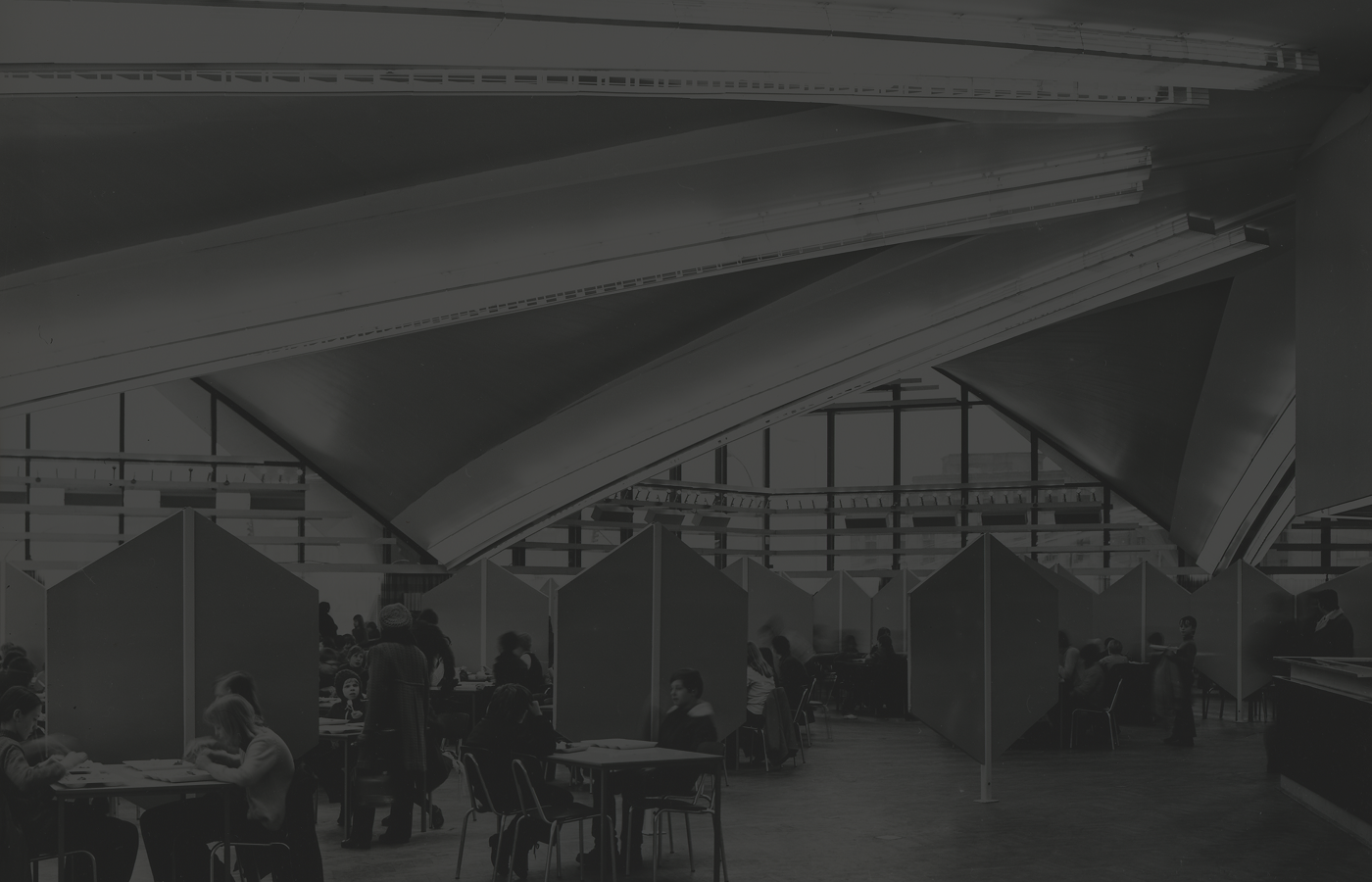
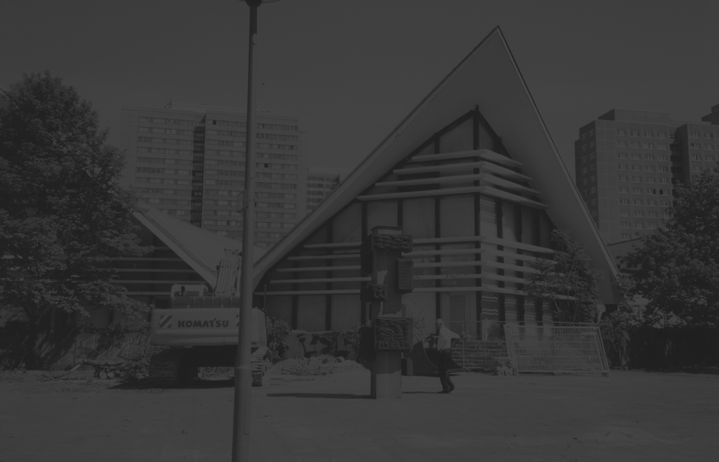
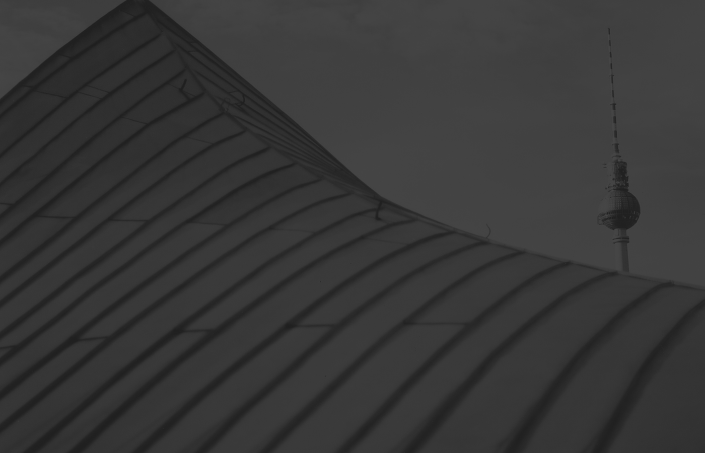
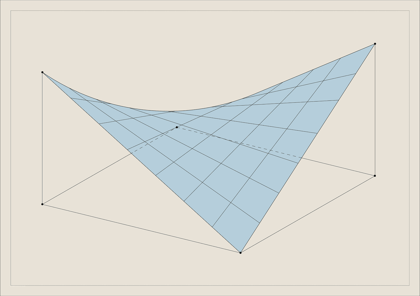
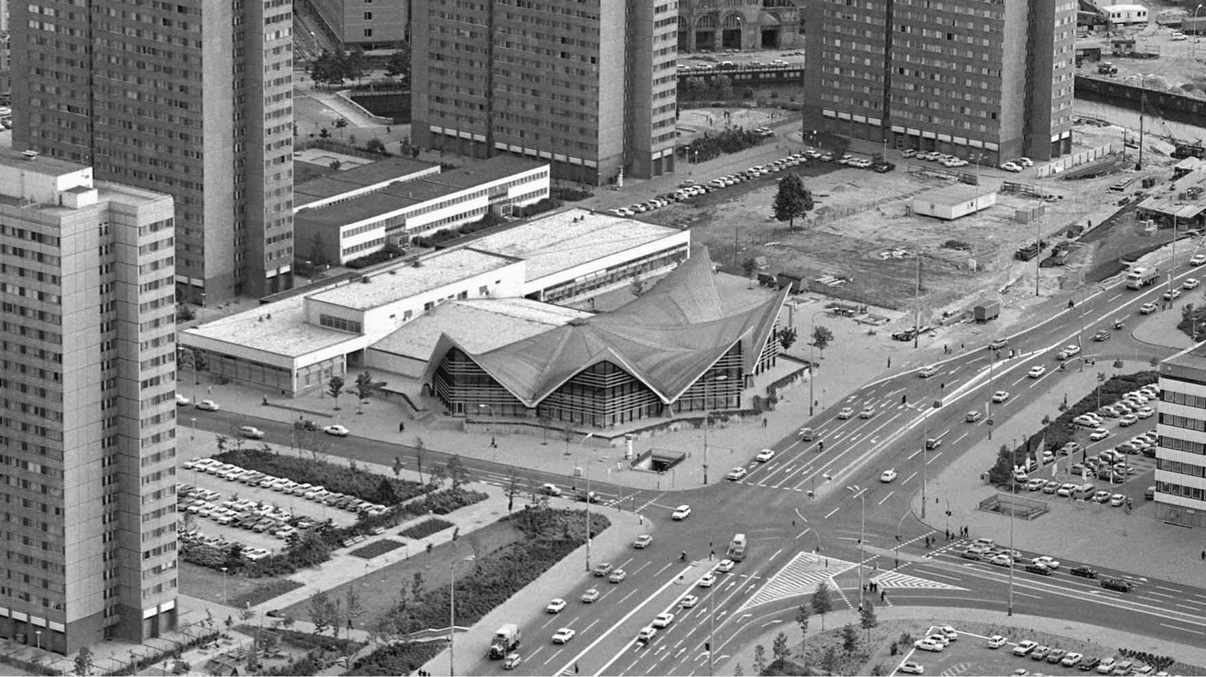
The demolition of the “Ahornblatt” restaurant in Berlin after German reunification sparked a heated debate about how to deal with the architectural heritage of the GDR. Many well-known structural engineers argued against its demolition, among them Jörg Schlaich:

“It would be a great loss for building culture if the Ahornblatt were demolished. We would not only once again sacrifice an outstanding example of the most material-appropriate and imaginative way of building with concrete to the logic of rationalization, but we would also destroy the living memory of an important component of our architectural culture.”
(from “Kühne Solitäre” by Wilfried Dechau)

The debate became a question of identity for the city: Should the history of the GDR and its architectural legacy remain part of Berlin’s shared urban identity?

Under then–Senate Building Director Hans Stimmann, Berlin embraced the idea of “critical reconstruction” – an urban design approach oriented toward historical street grids and traditional building typologies. This return to premodern forms led to the devaluation of GDR architecture and, with it, of the lived realities of many East Germans. In this context, the “Ahornblatt” was ultimately demolished and replaced with perimeter block development.

Today, the debate about how to deal with GDR architecture has flared up again – it is no longer regarded merely as a museum relic.

Let’s talk

Collaborate
with us

You have ideas for the content development of the museum and would like to exchange thoughts with us? We’d love to hear from you!

Collaborate as a Museum

Your museum is interested in a partnership? We offer a curated exhibition that we’d be happy to bring to your institution. Get in touch – we look forward to working together!

Become
a Partner

You’re passionate about structural engineering and believe in the importance of sharing it with others? We have big plans and are looking for committed partners. We’d love to hear from you!