NEW STRUCTURE RECOVERED: The Berlin "Bauakademie" has been online since April 20. Enjoy exploring it!

The

Cable Net 
Cooling Tower

The cable net cooling tower is a supporting structure that achieves stability solely through prestressing and optimal geometric form. It impressively demonstrates what is possible when function and form coincide - or as Jörg Schlaich put it: ‘It (the form) is definitely its (the tower’s) true face, its true form, because function and form coincide.

1973 - 1974

In less than two years, a visionary concept becomes reality: with the cable-net cooling tower, a groundbreaking new structural principle for cooling towers was developed between 1973 and 1974. The construction followed an innovative principle - the supporting structure was pre-assembled on the ground and gradually raised hydraulically to its final height.

540 Cables

The cable net structure consists of exactly 540 high-strength steel cables. Of these, 216 vertical meridian cables and 108 left and 108 right diagonal cables form a tensioned membrane stretched between a lower foundation ring and an upper steel ring. Like an Advent wreath, this hangs from a central concrete mast by means of 36 cables. Inside, 2 spoke-wheels also stiffen the cable net with
36 cables each.

58000 kN

The entire cable net is pre-tensioned with 58,000 kilonewtons - this corresponds to the weight of around 700 full-grown elephants pulling on the cables together. This enormous pre-tensioning, as well as the form make the supporting structure permanently rigid and resistant to wind loads.

1991

The cable net cooling tower was blown up in 1991. It was part of the Hamm-Uentrop thorium high-temperature reactor, a prestige project that did not prove itself economically or technically. After protests, breakdowns and decommissioning, the symbol of an ambitious reactor line became a memorial. Dismantling began - and with it an exceptional piece of the art of engineering was lost.

The cable net cooling tower is a supporting structure that achieves stability solely through prestressing and optimal geometric form. It impressively demonstrates what is possible when function and form coincide - or as Jörg Schlaich put it: ‘It (the form) is definitely its (the tower’s) true face, its true form, because function and form coincide.

The Cable Net Cooling Tower

yr 1974-1991

  • Historical Background
  • History of use
  • Ownership History
  • Architectural Features
  • With the goal of developing water-free cooling systems for future generations of power plants, dry cooling gained increasing importance during the 1960s and 70s This took place against a backdrop of global water scarcity and growing environmental requirements—the aim was to use no or less water for the cooling process and, in particular, to ensure that no warm water was returned to the ecosystem.

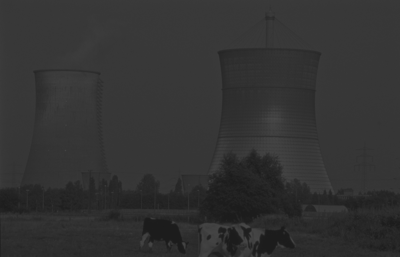
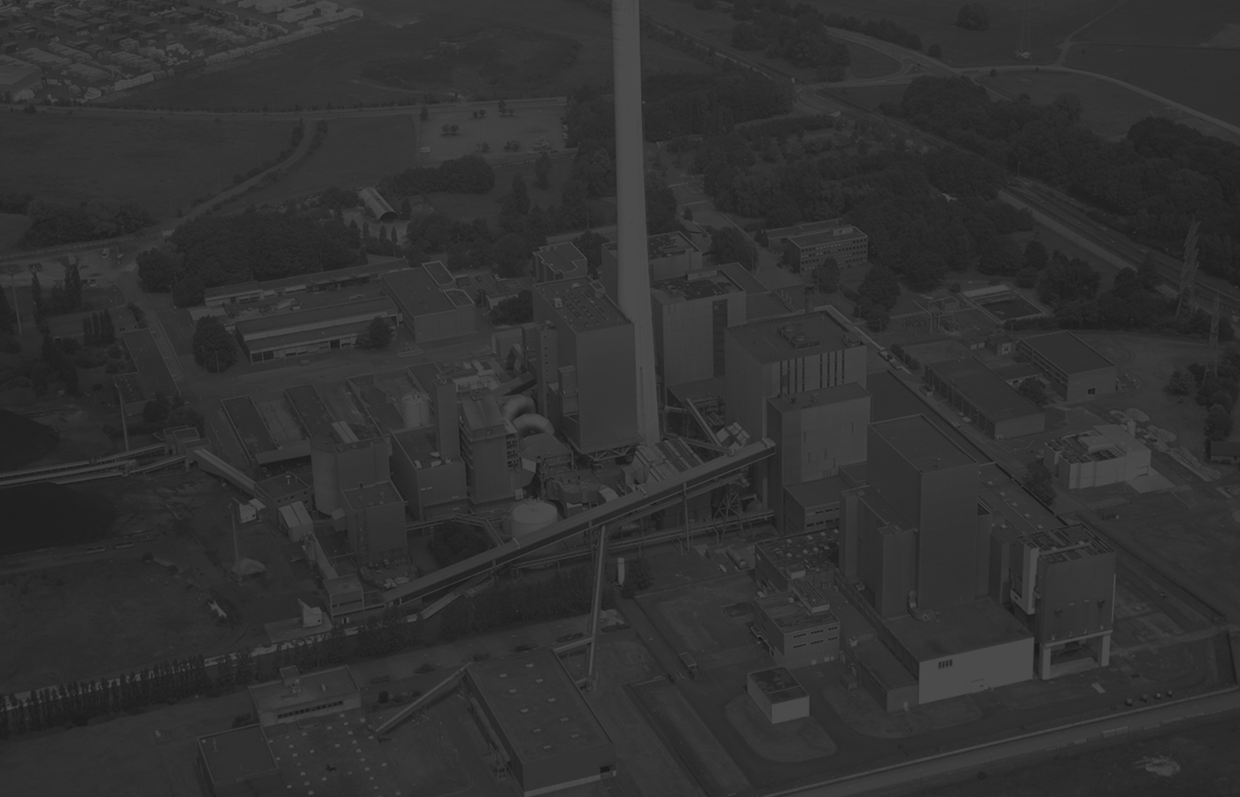
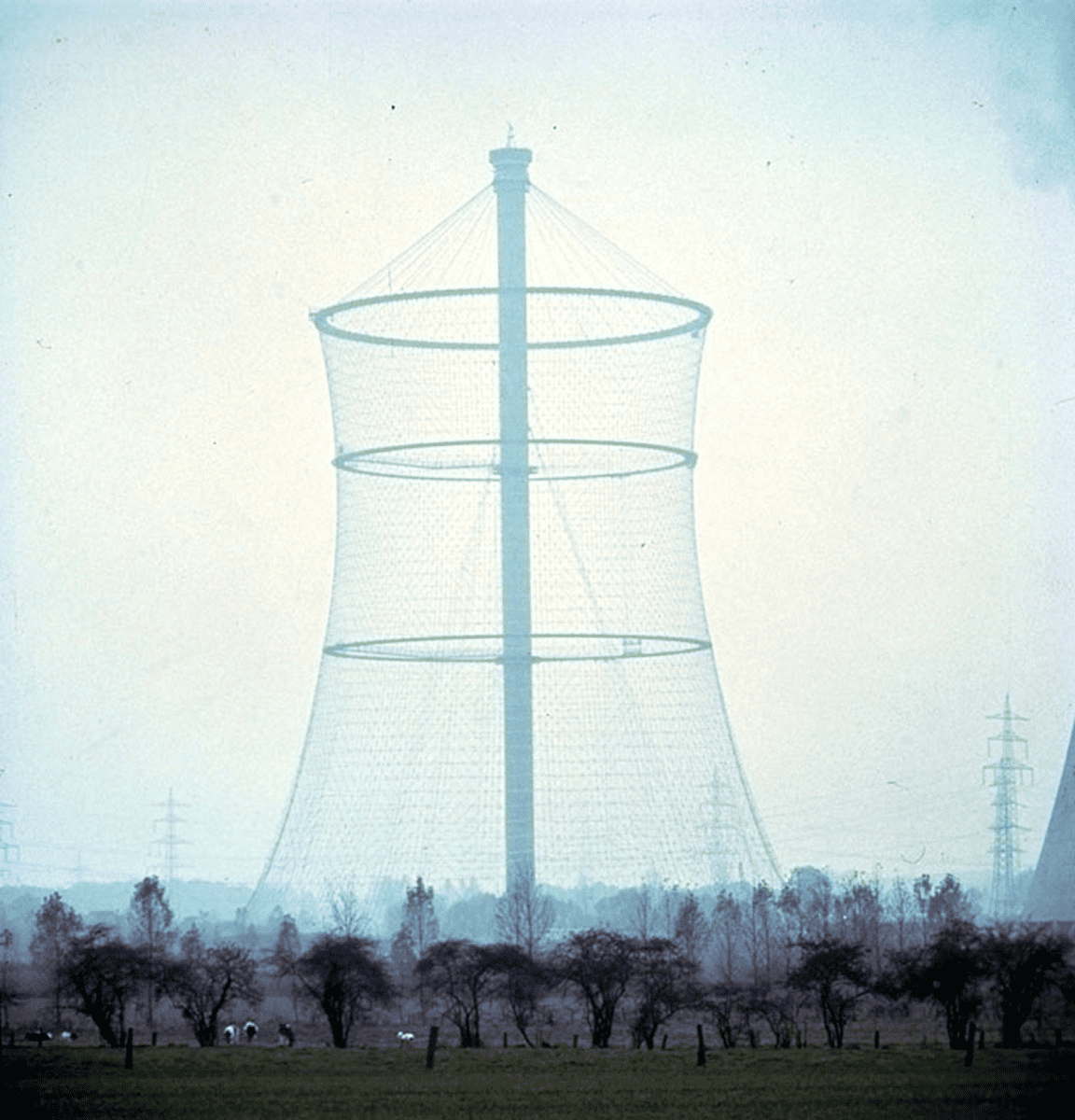
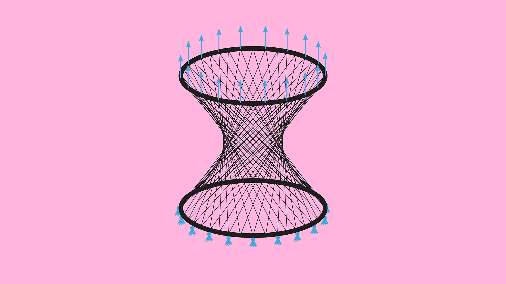
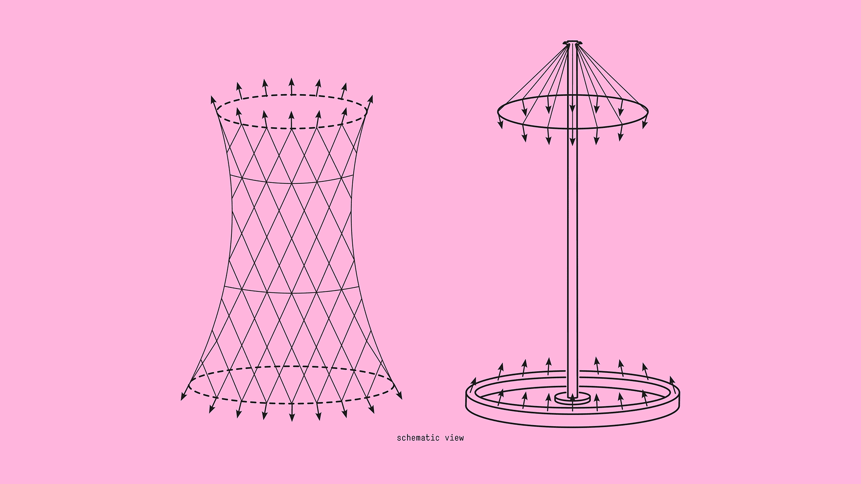
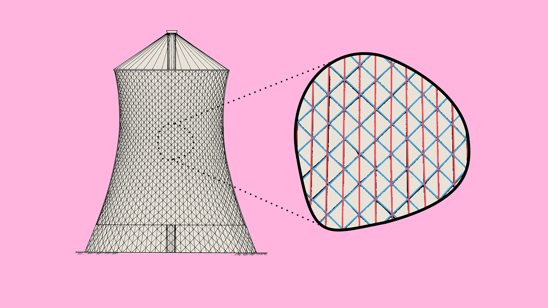
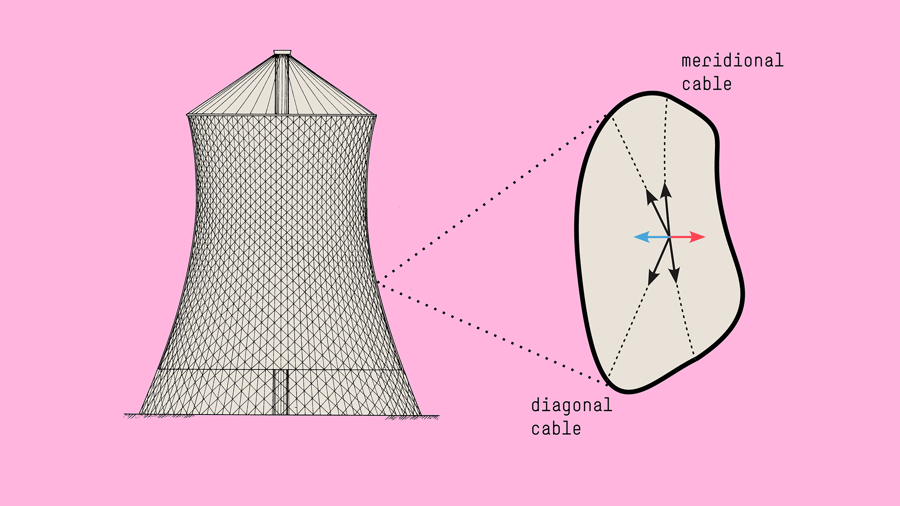
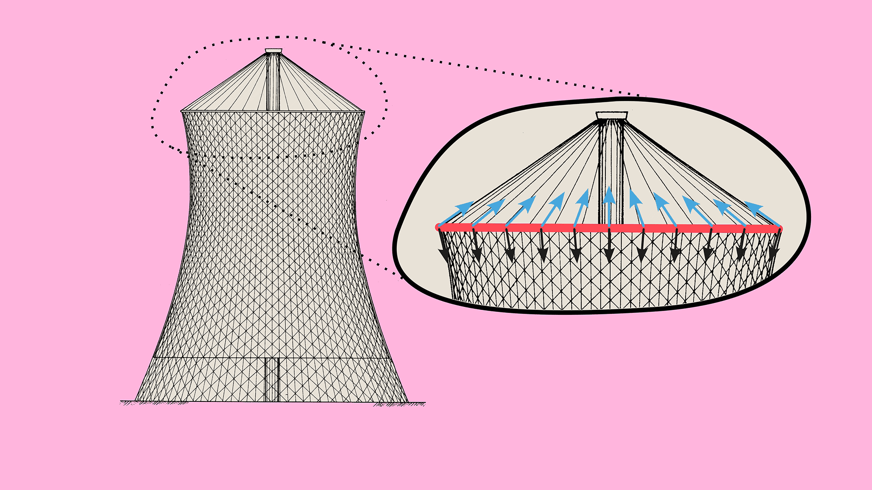
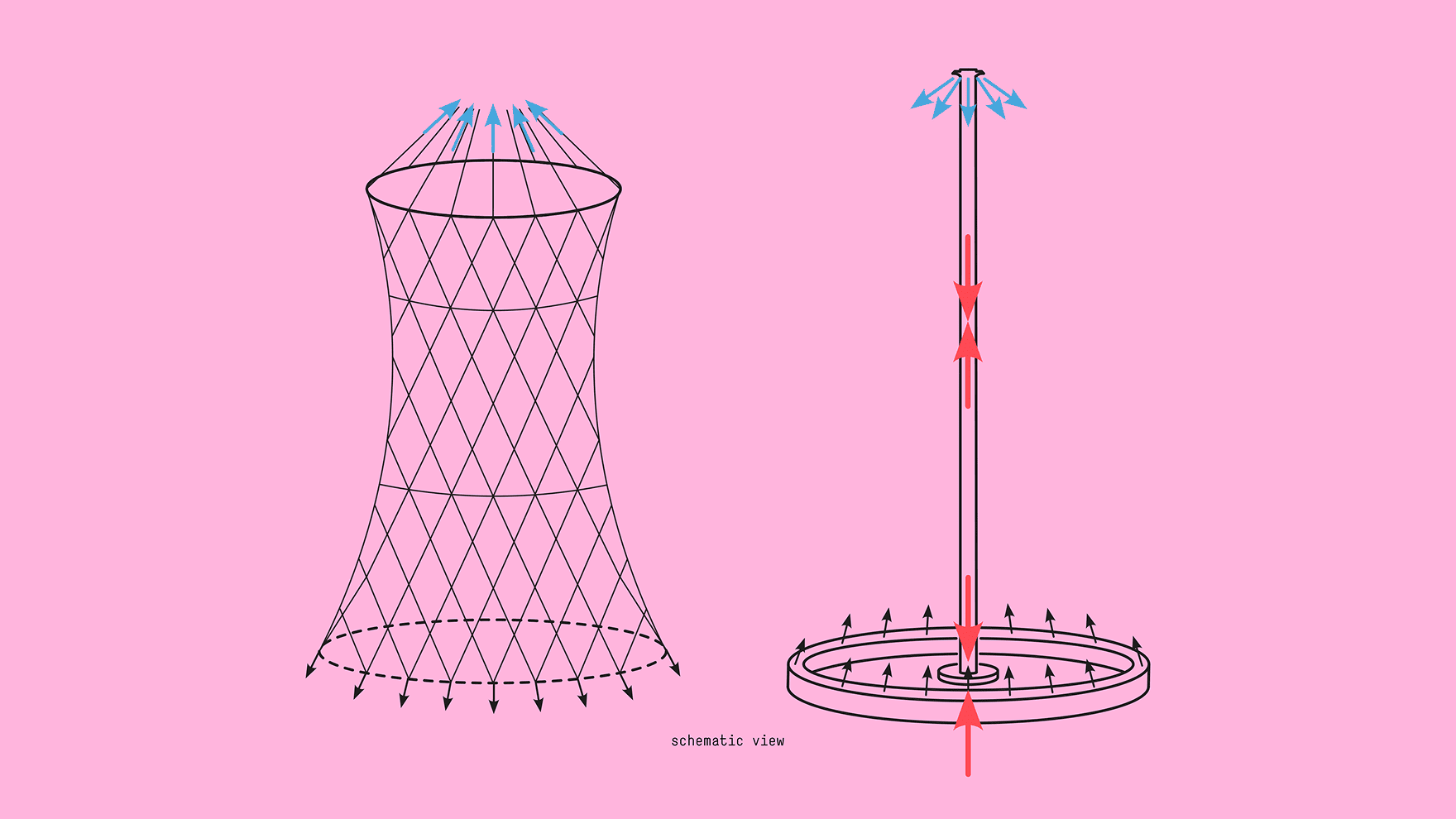
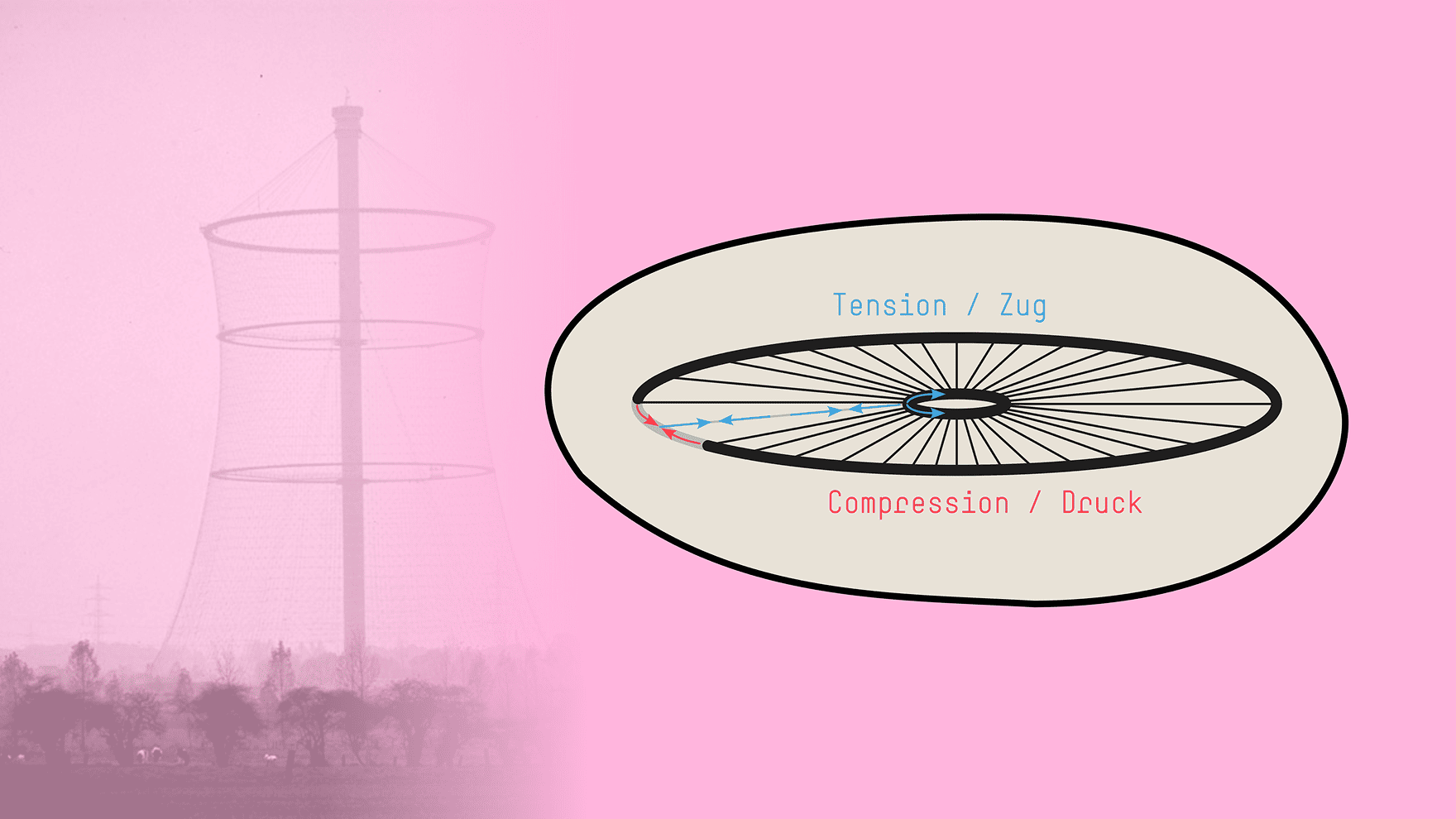
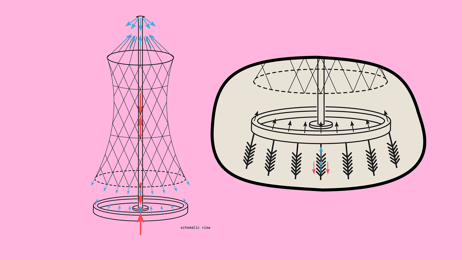
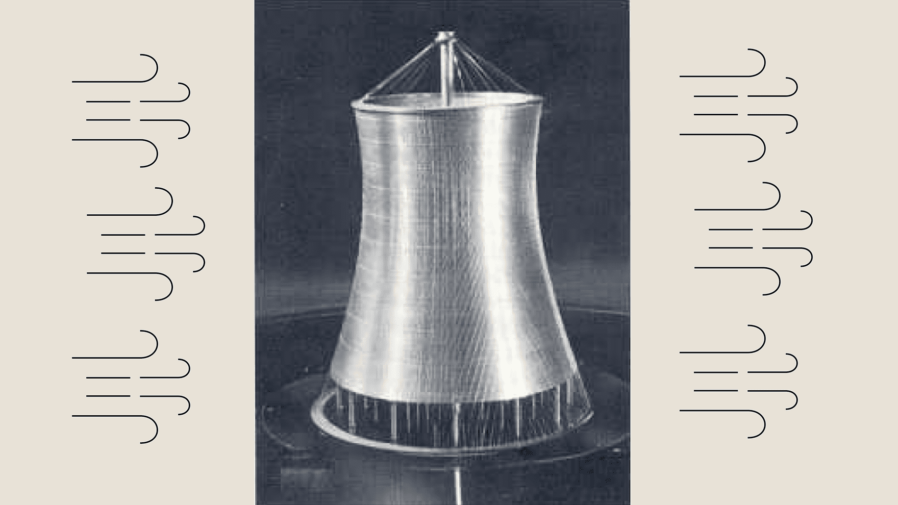
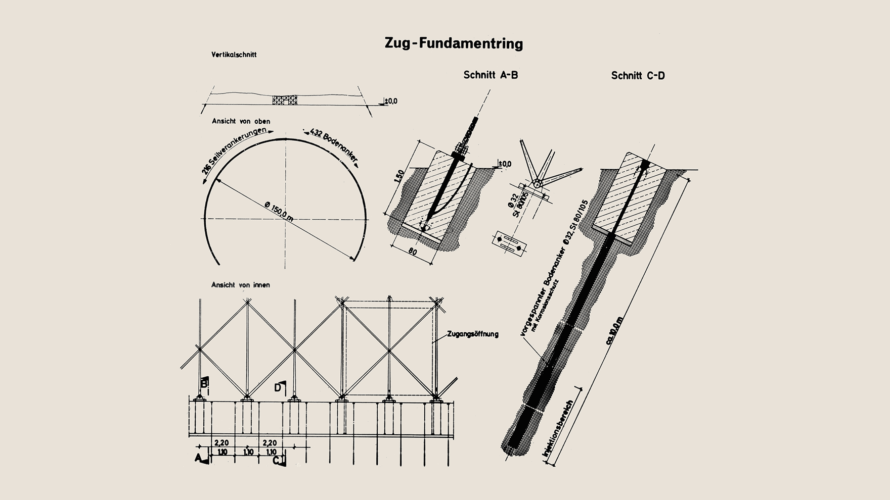
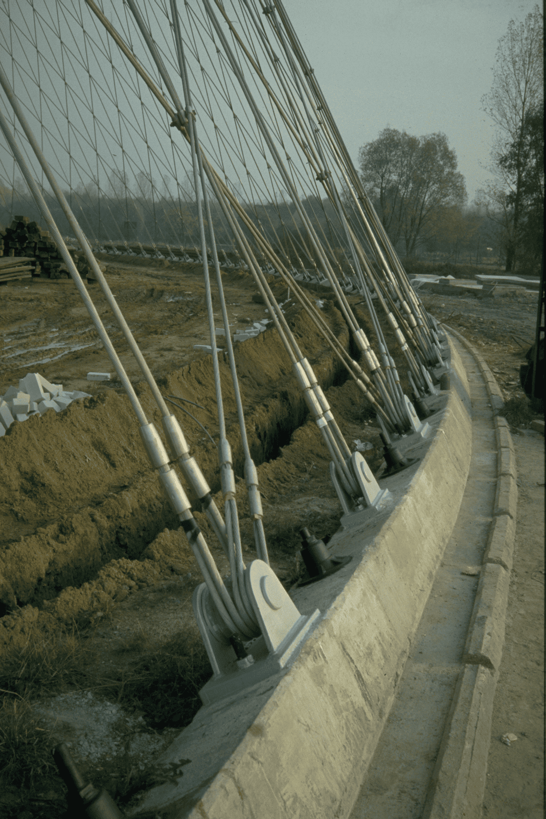
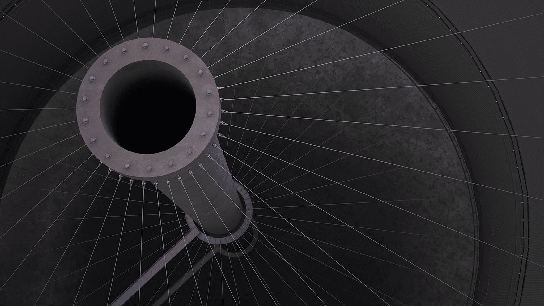
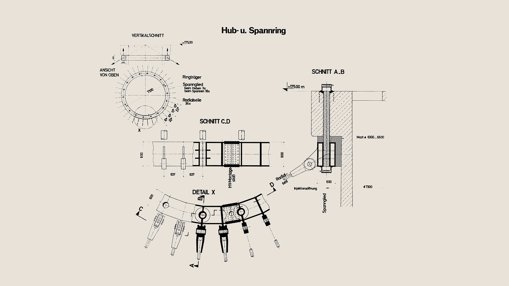
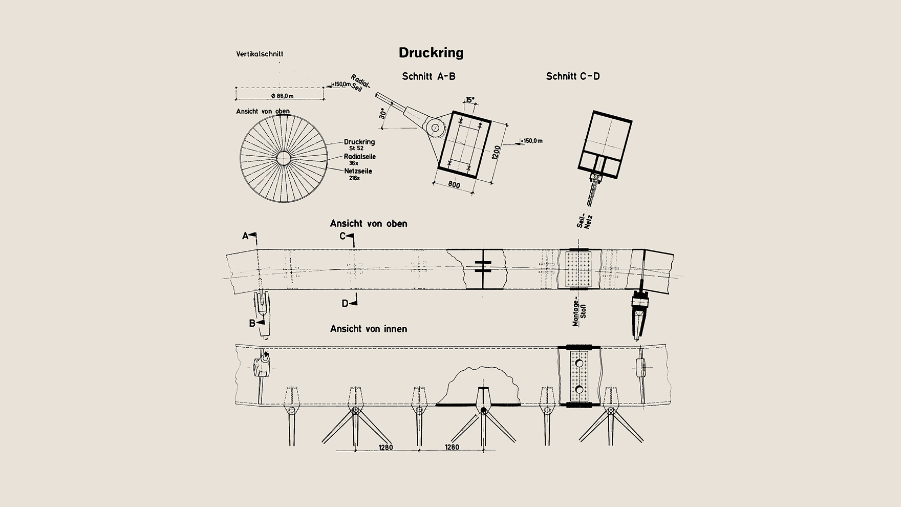
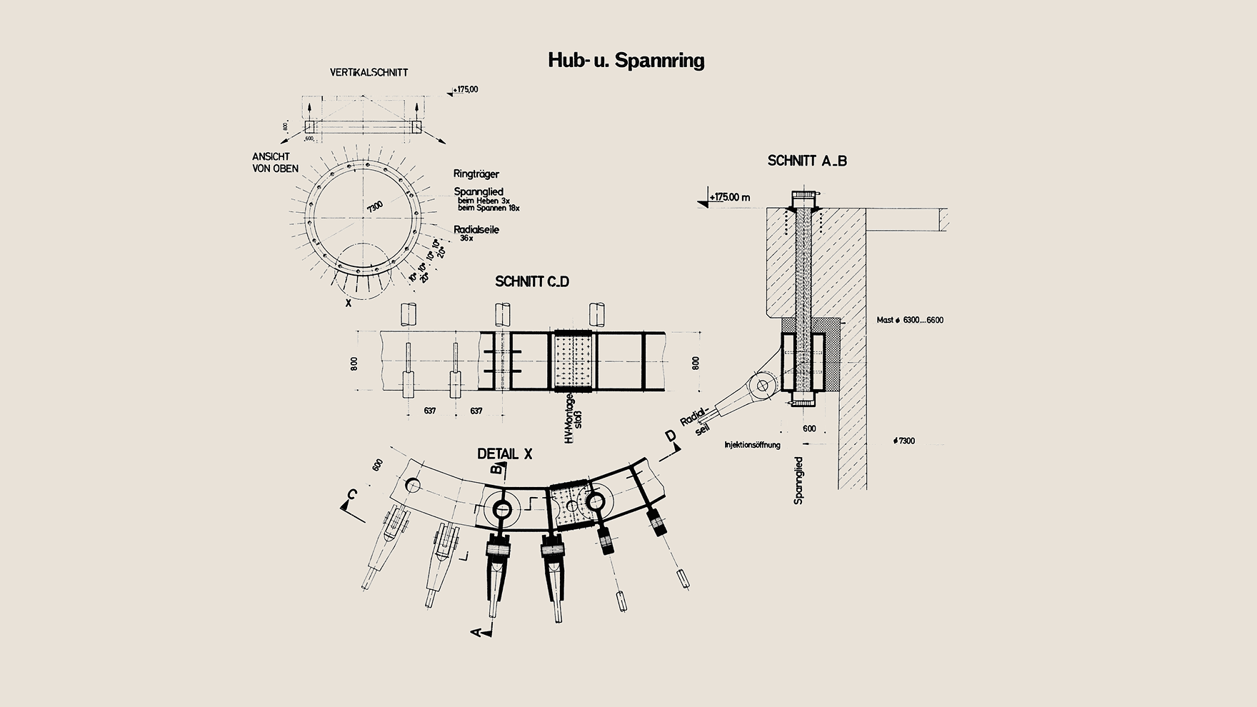
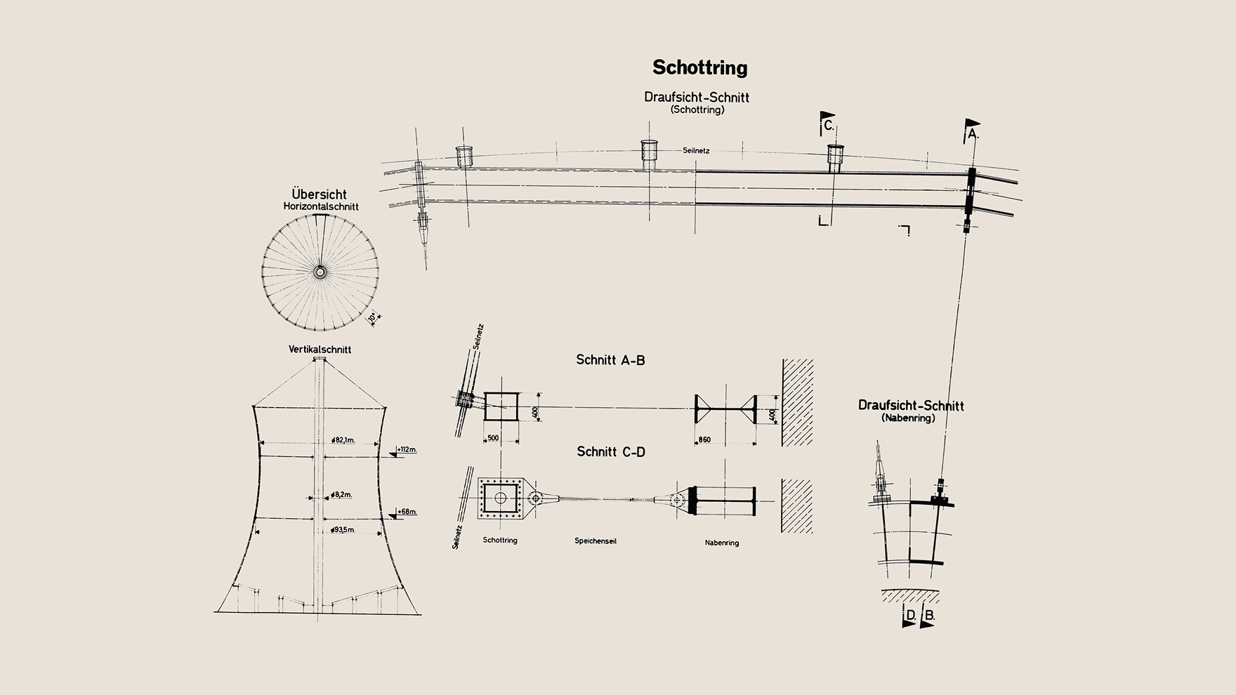
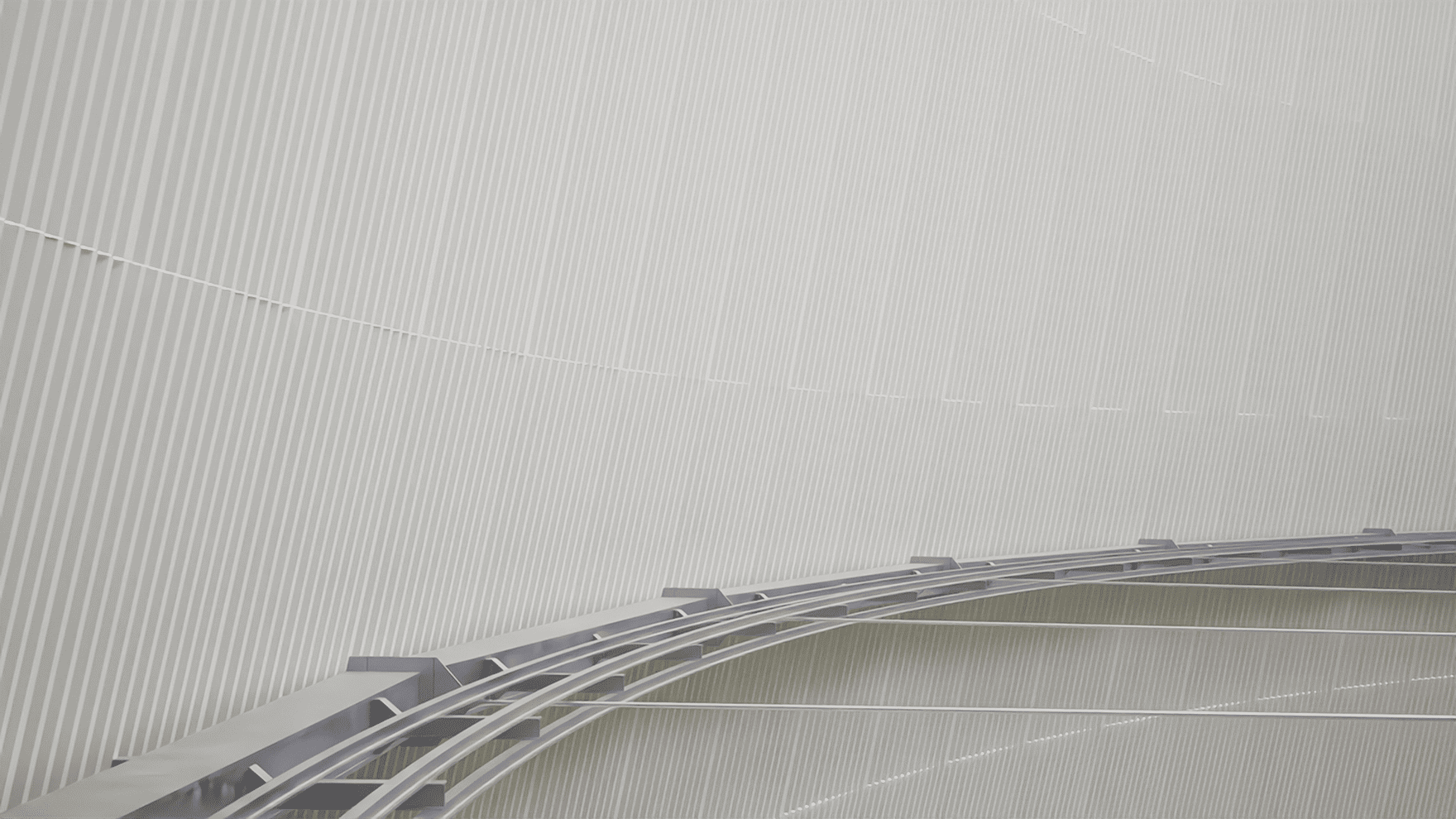
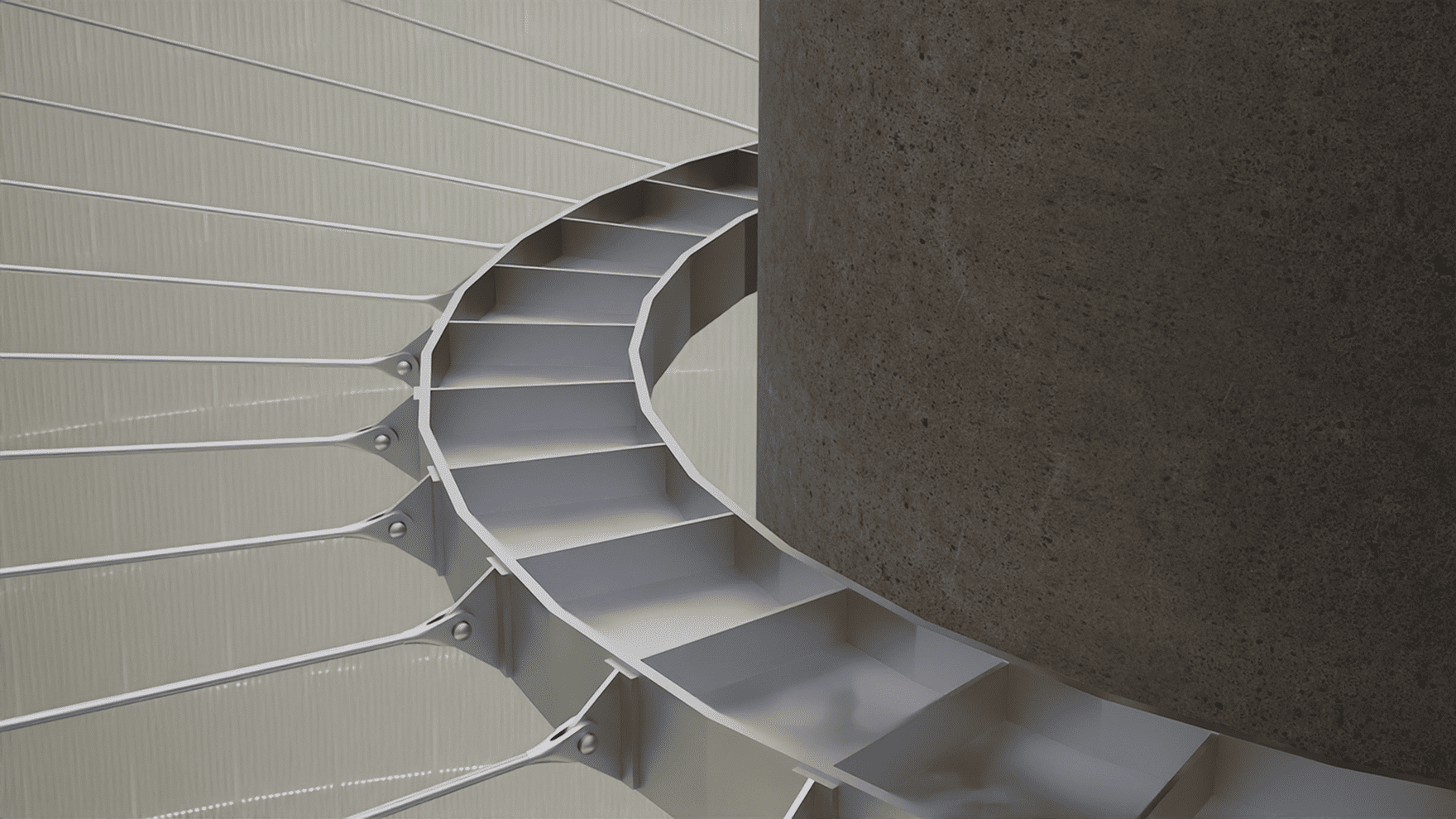
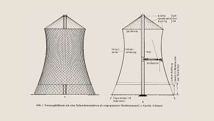
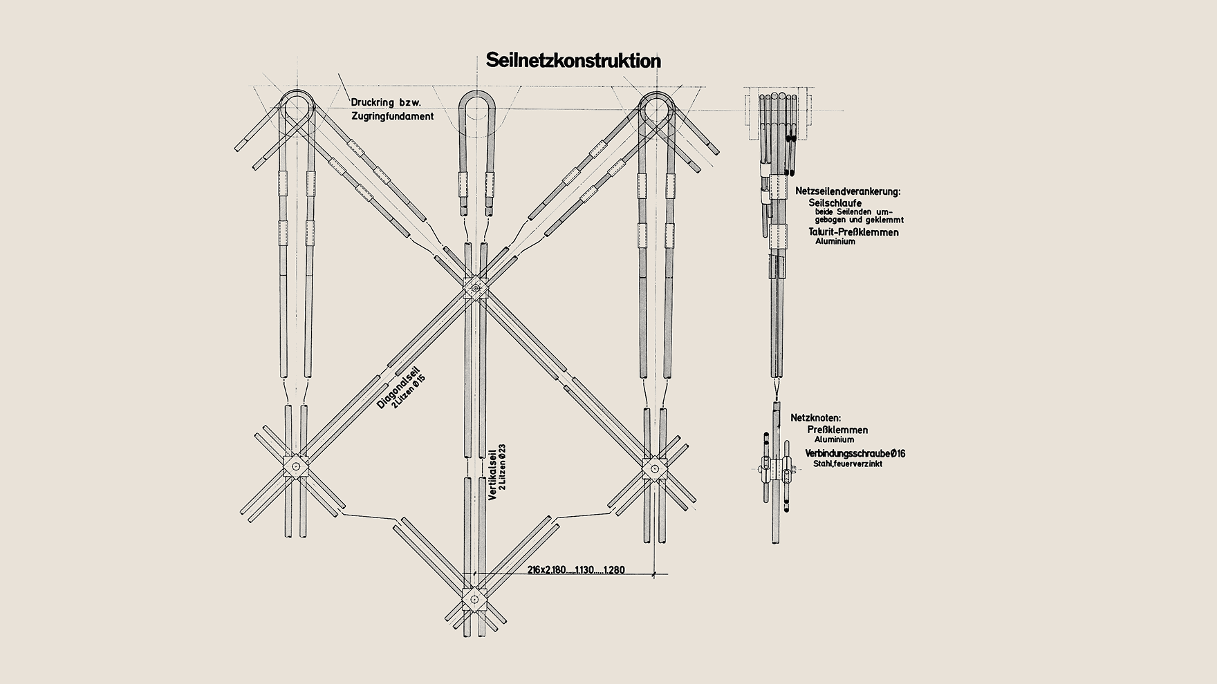
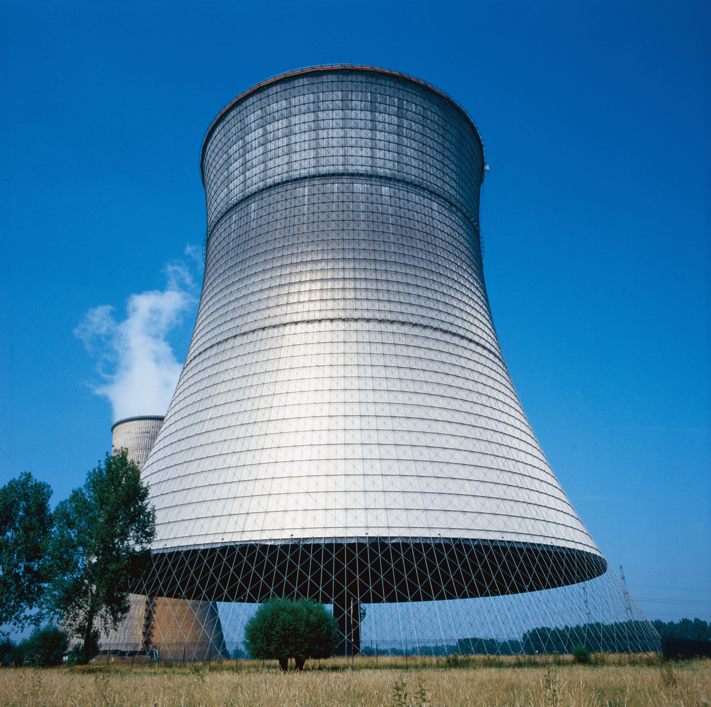
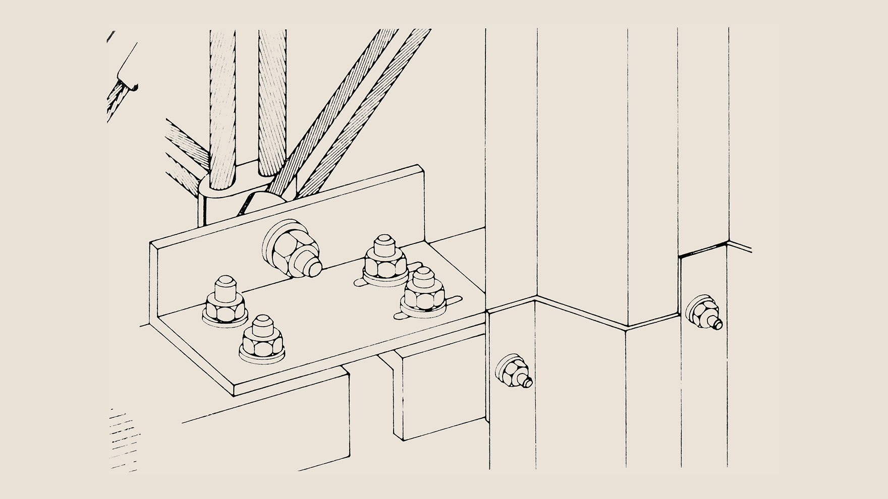
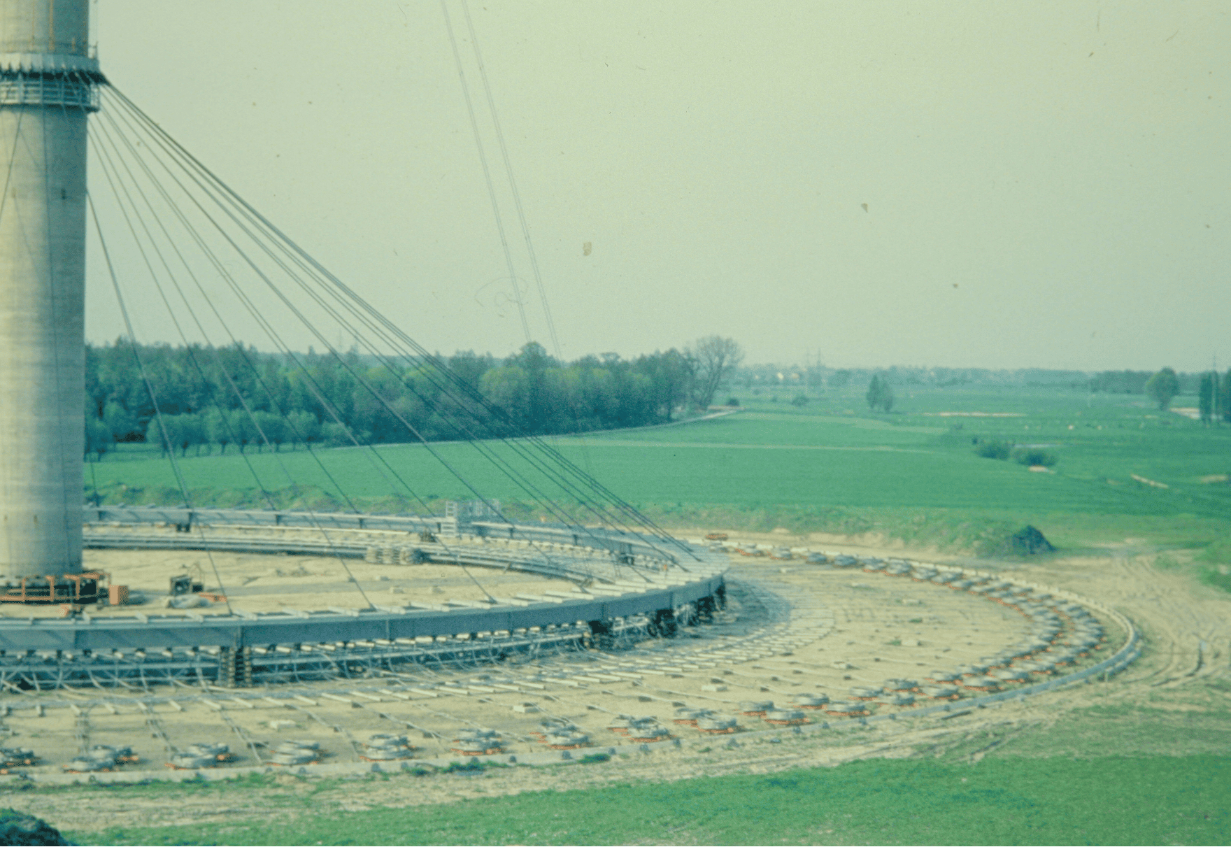
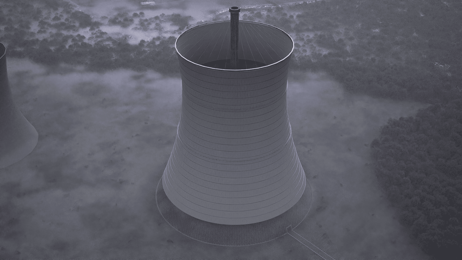
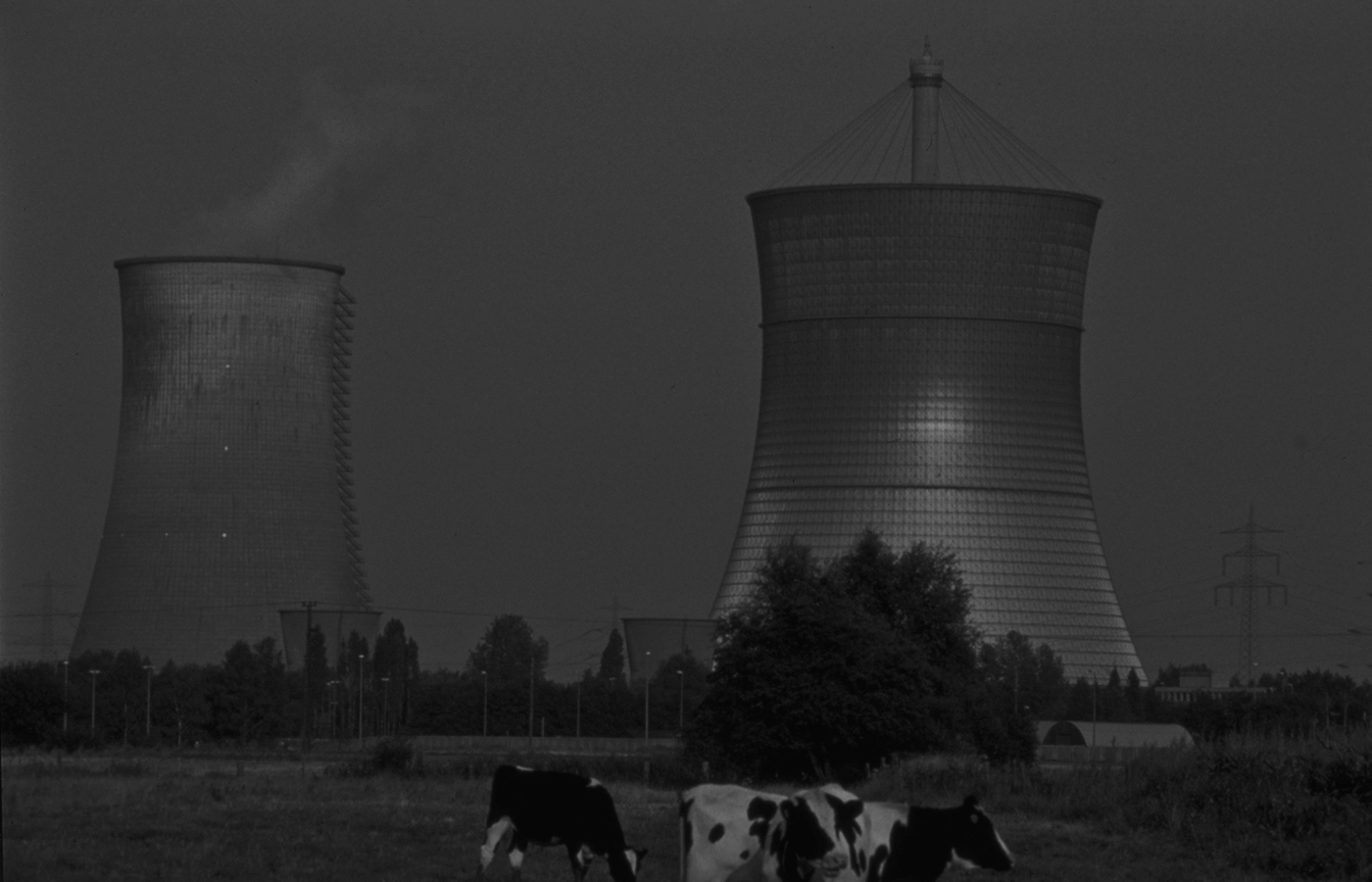
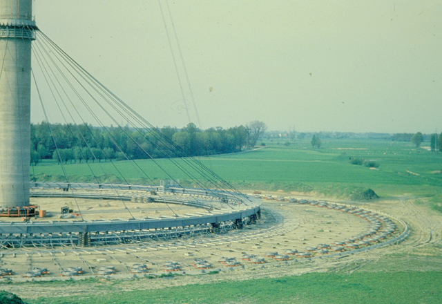
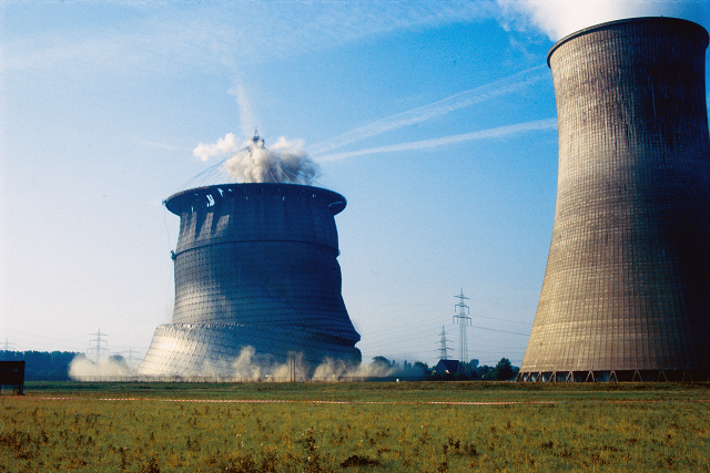
    Since dry cooling systems inherently require significantly larger structural volumes, traditional reinforced concrete shells reached their economic and technological limits. The cable-net cooling tower emerged as a response to this shift: a novel, prestressed cable-net membrane enabled a lighter and significantly taller tower structure for the first time
  • The cable net cooling tower served as a prototype for waste heat dissipation from the Hamm-Uentrop high-temperature nuclear power plant (THTR 300) from 1986 to 1989. With its shutdown the tower also lost its function. Widespread use remained limited, as dry cooling loses efficiency at high ambient temperatures and involves considerable technical complexity. In Germany, this method remained a one-time experiment with the cable net cooling tower. Nevertheless, the prestressed cable net structure provided a feasible solution for tower heights and diameters of up to 300 m for the first time.
  • The construction was commissioned by “Hochtemperatur-Kernkraftwerk GmbH” - an operating company with the participation of several energy suppliers, in particular “Vereinigte Elektrizitätswerke Westfalen”. As this was a technologically pioneering pilot project, the state of North Rhine-Westphalia also supported the project financially.
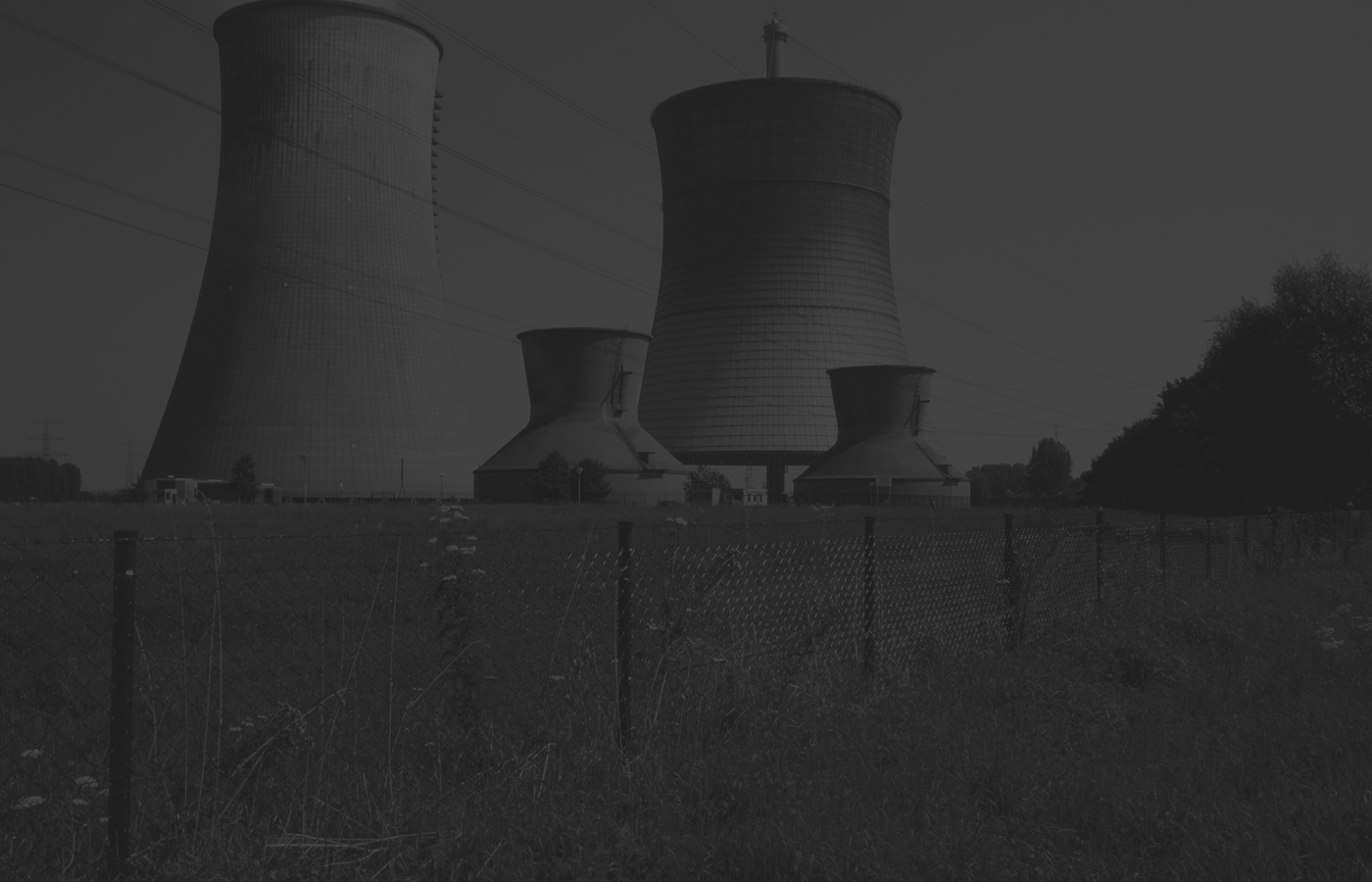
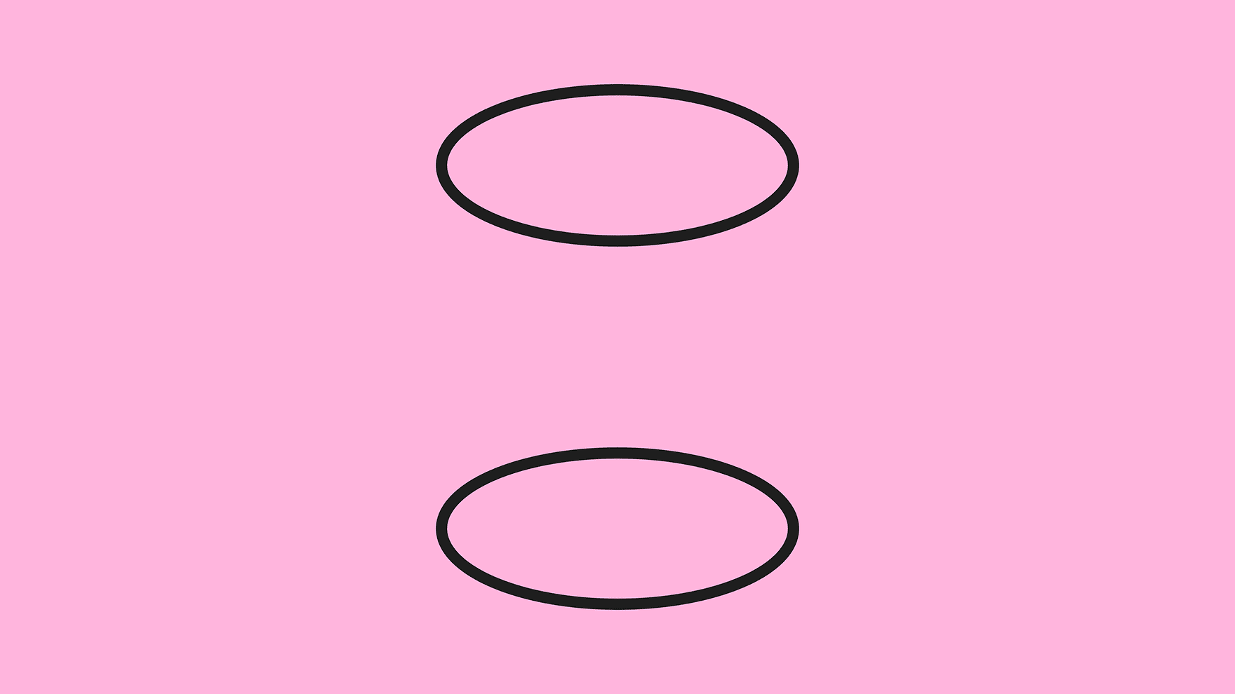
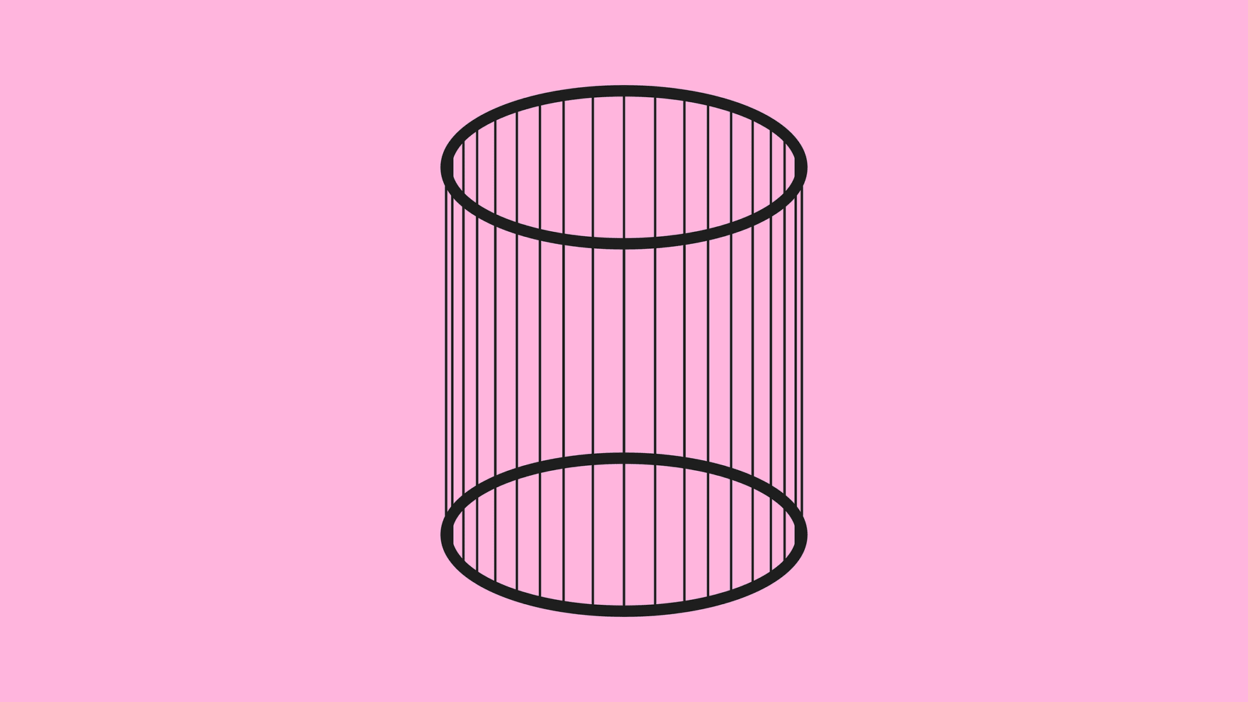
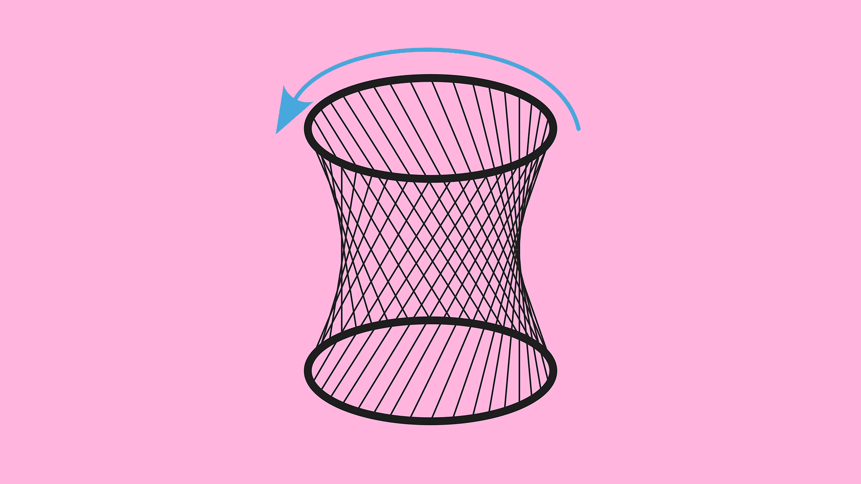
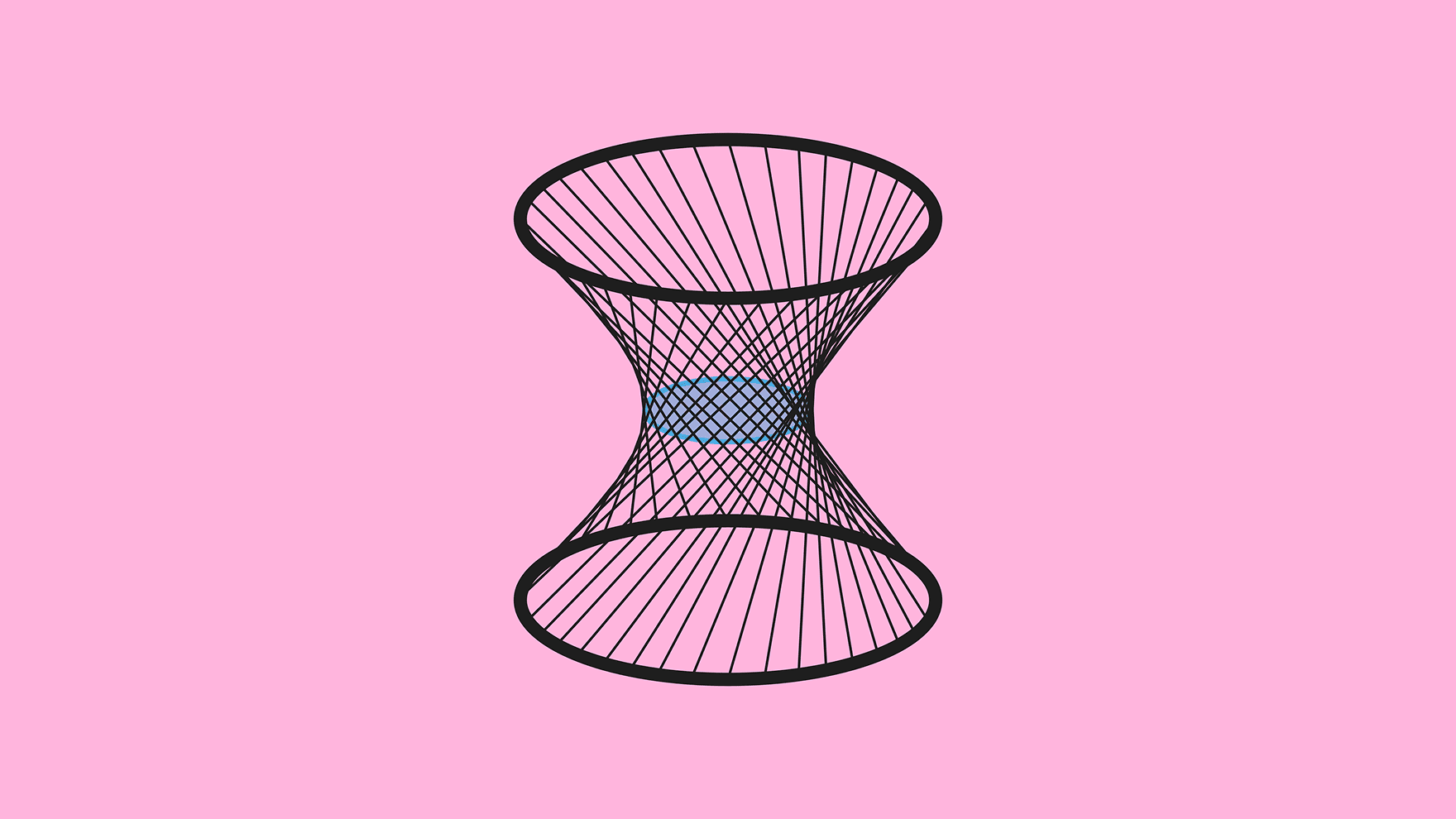
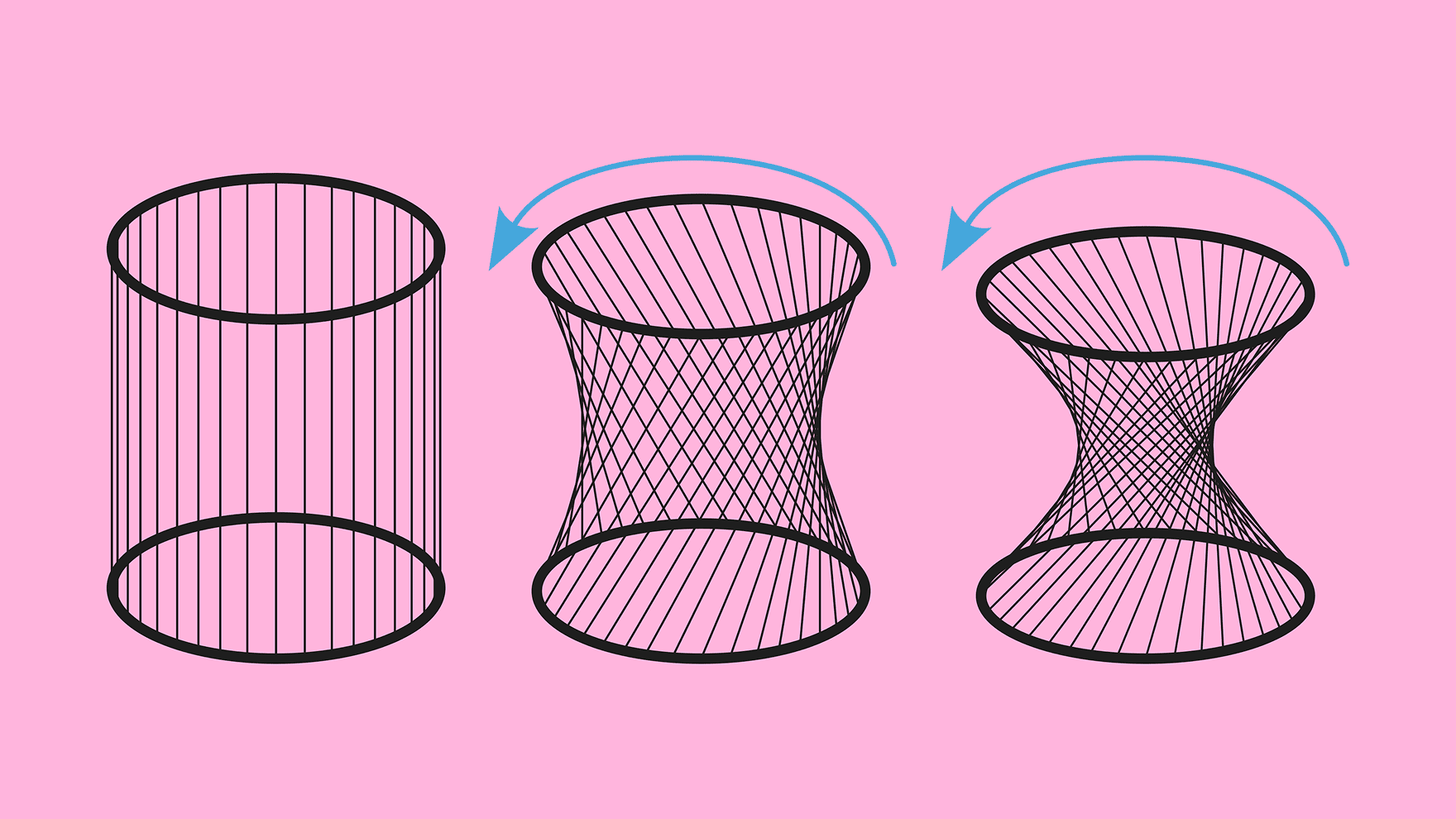
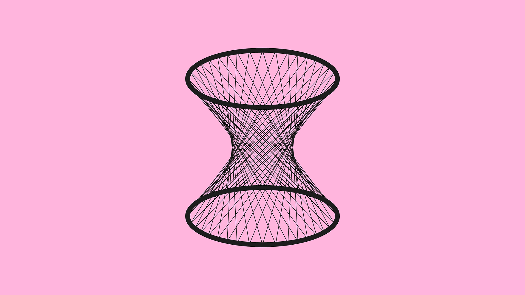
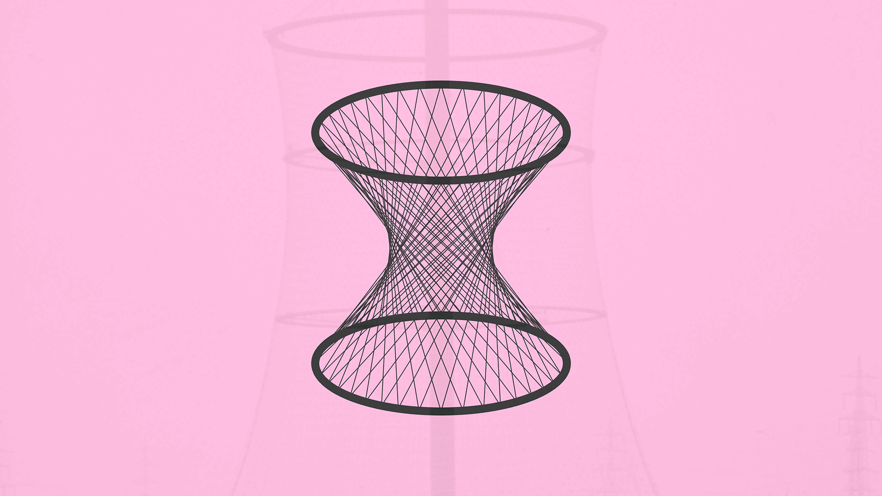
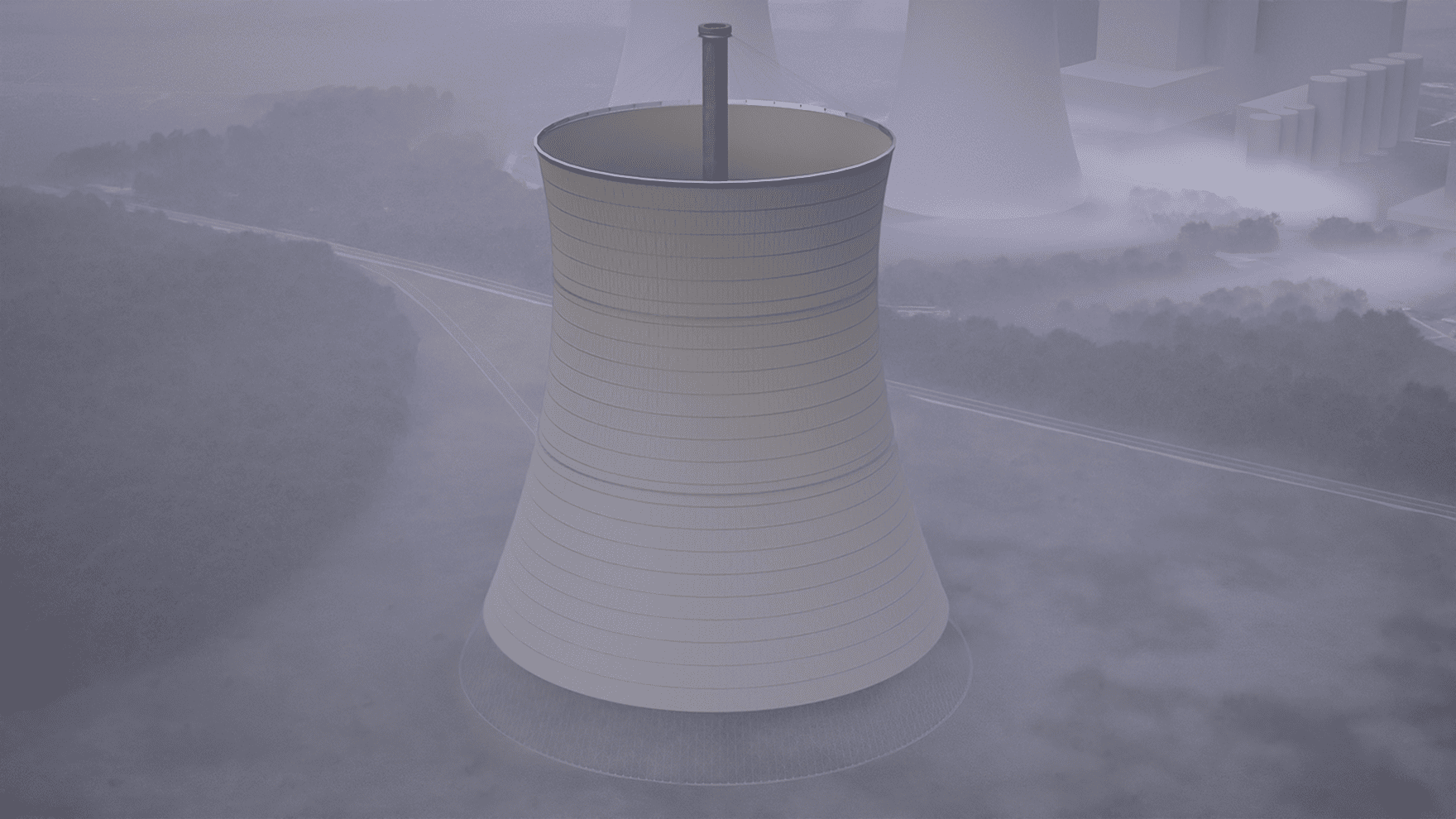
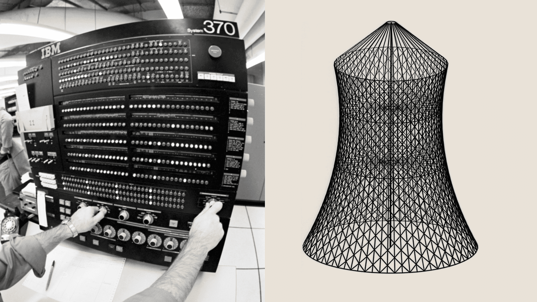
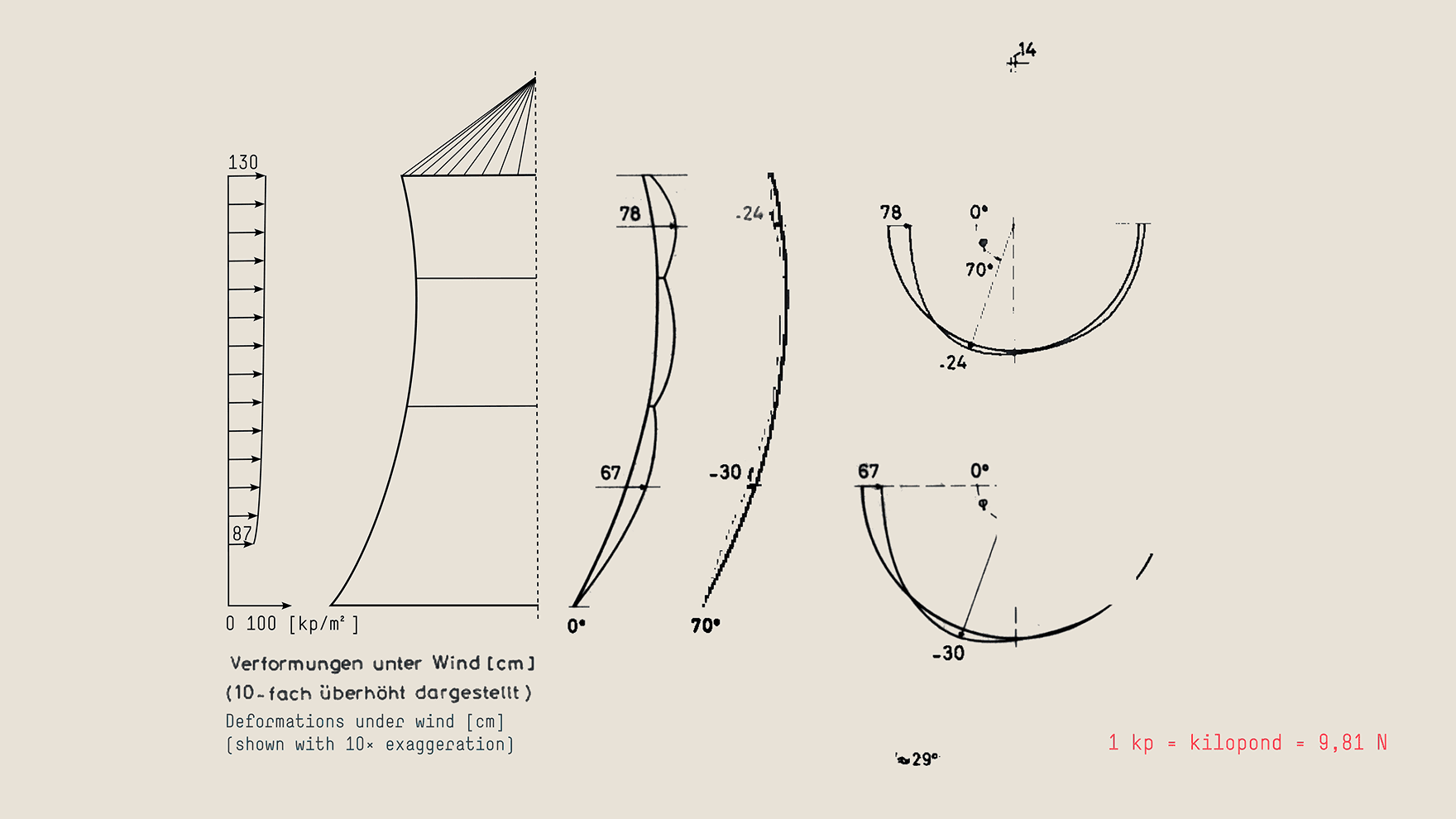
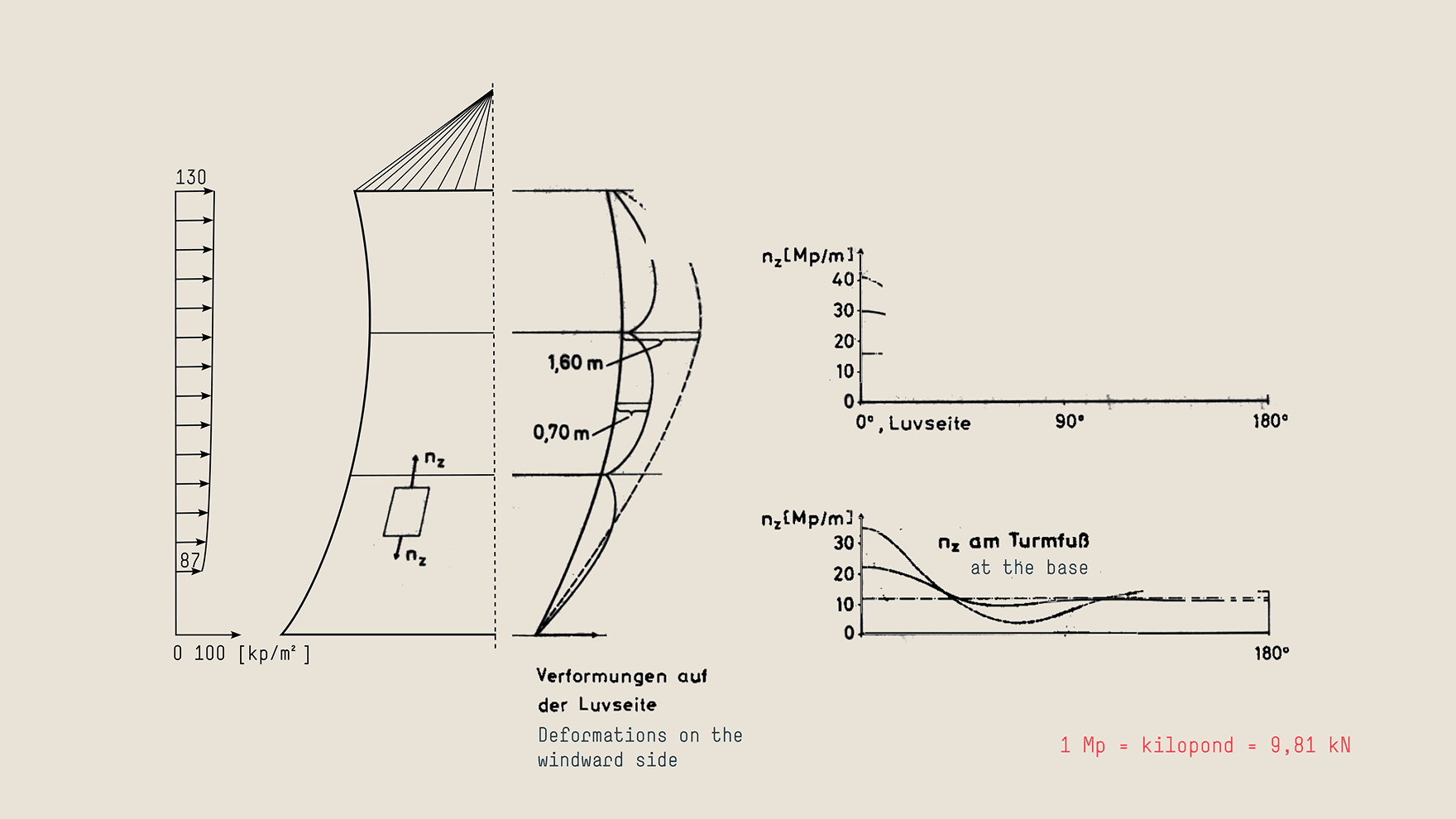
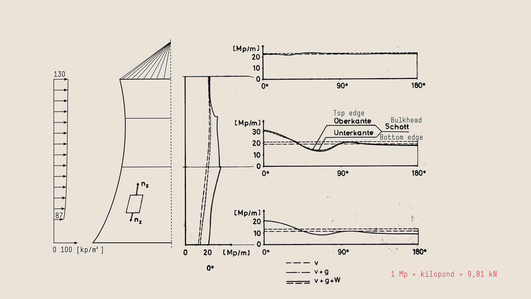
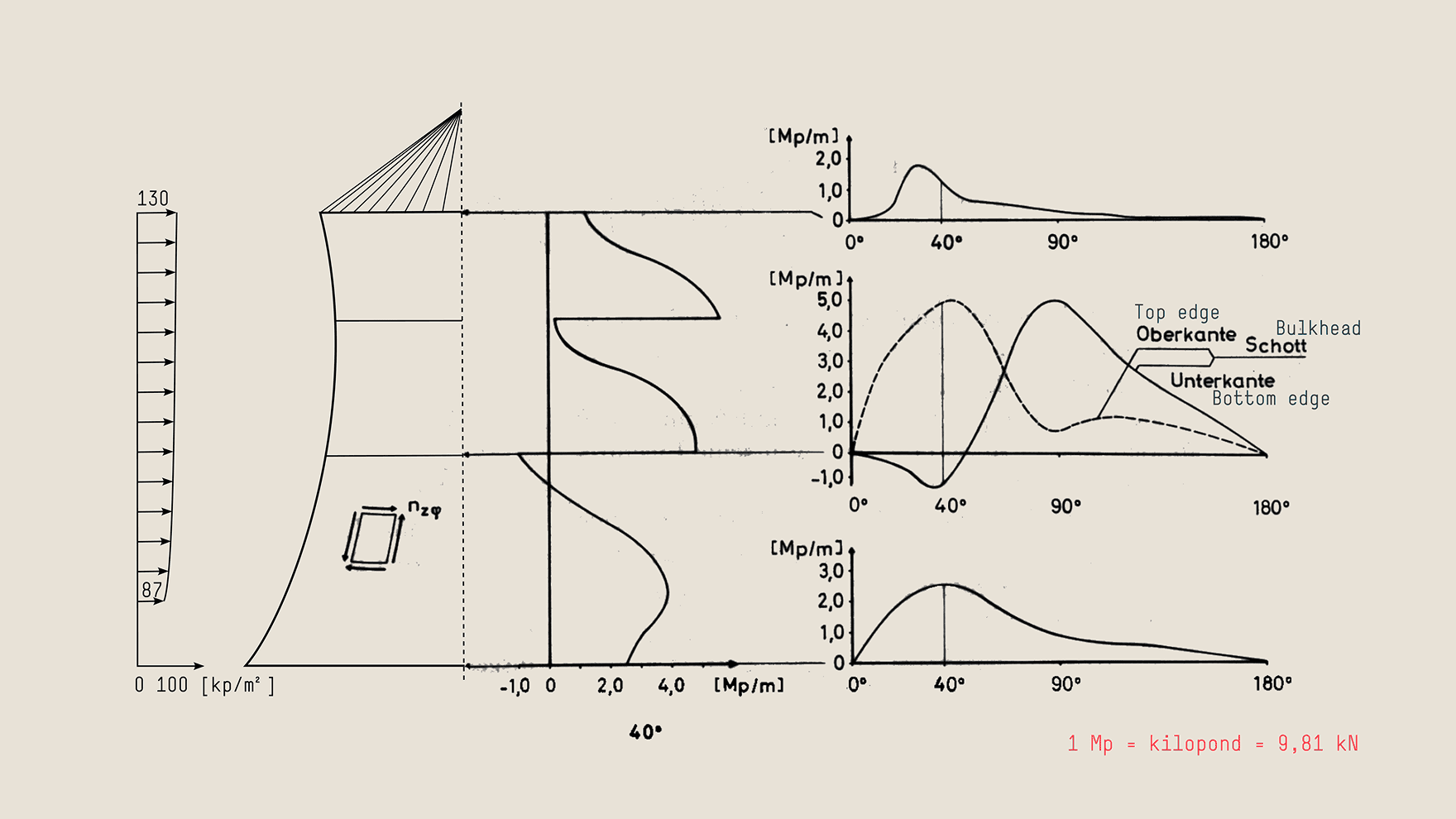
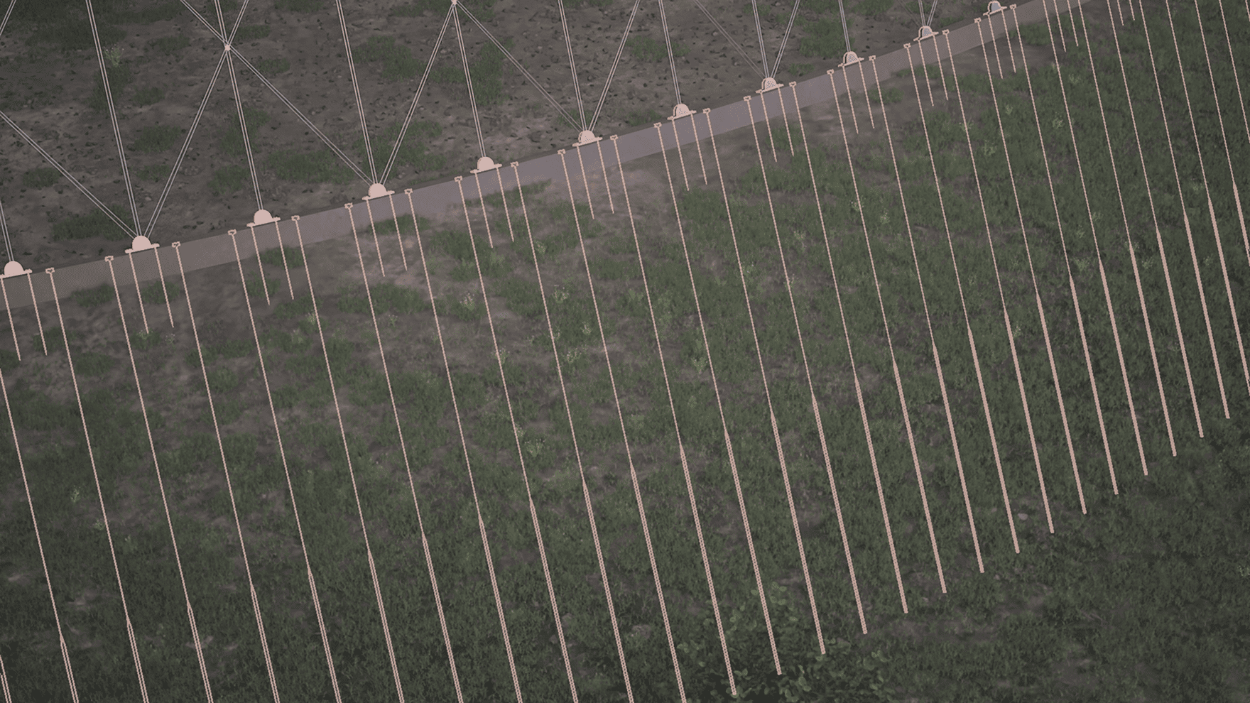
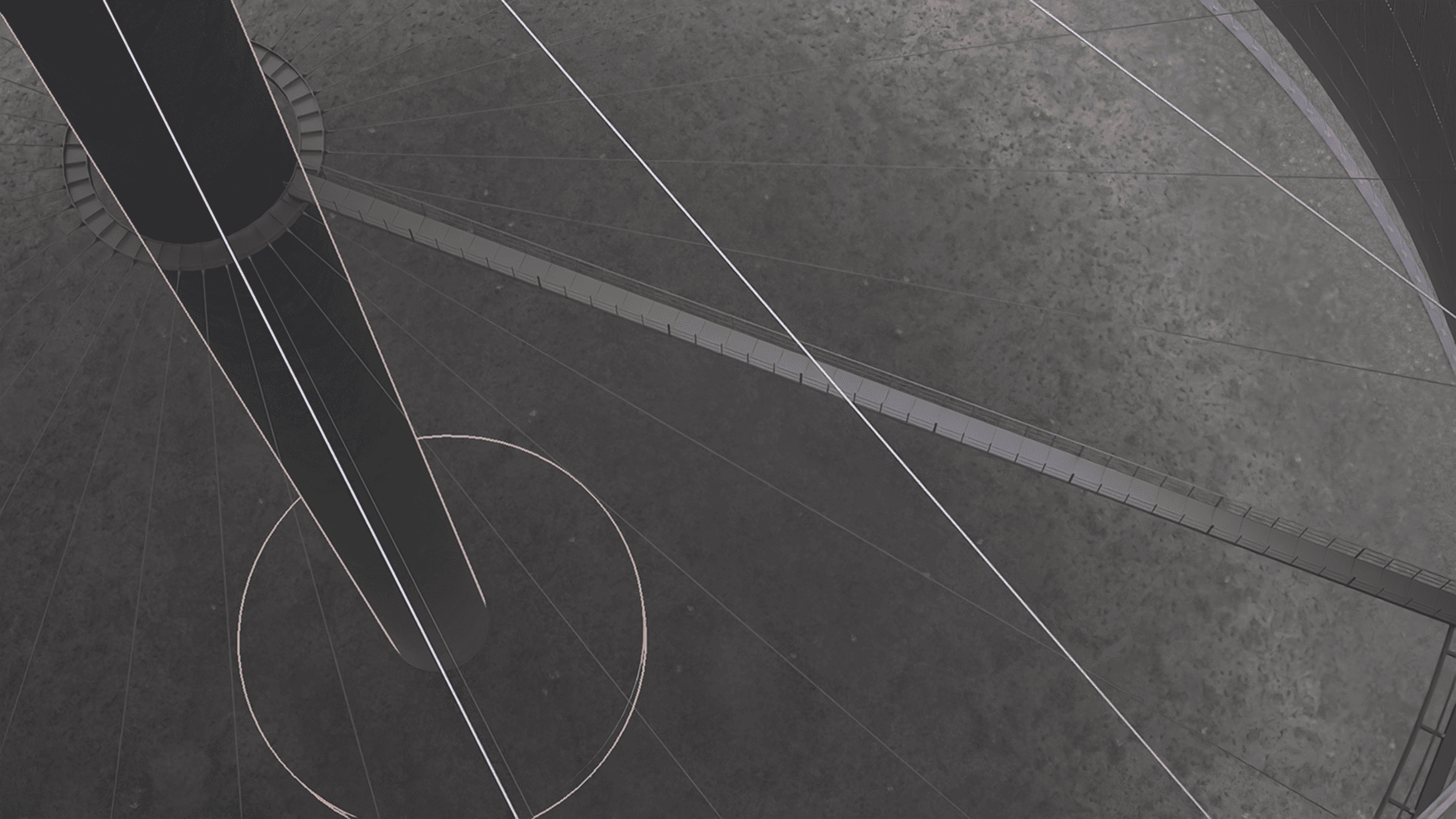
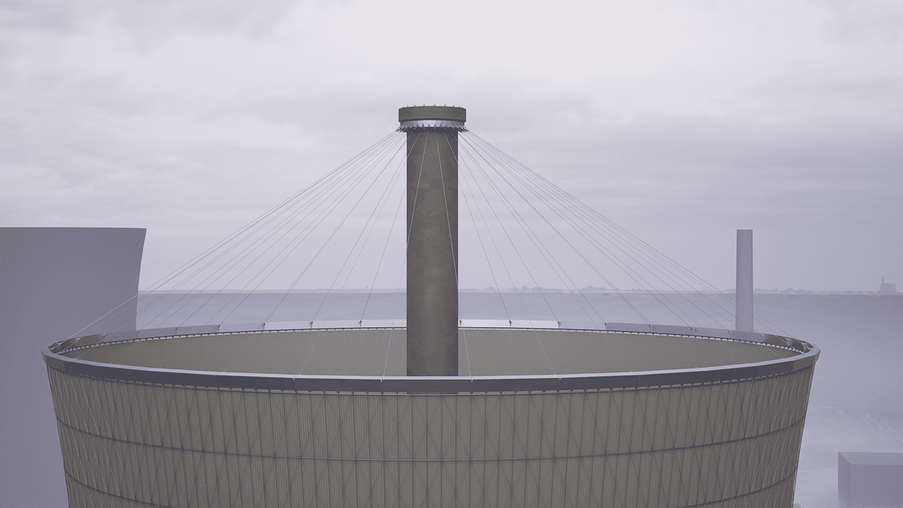
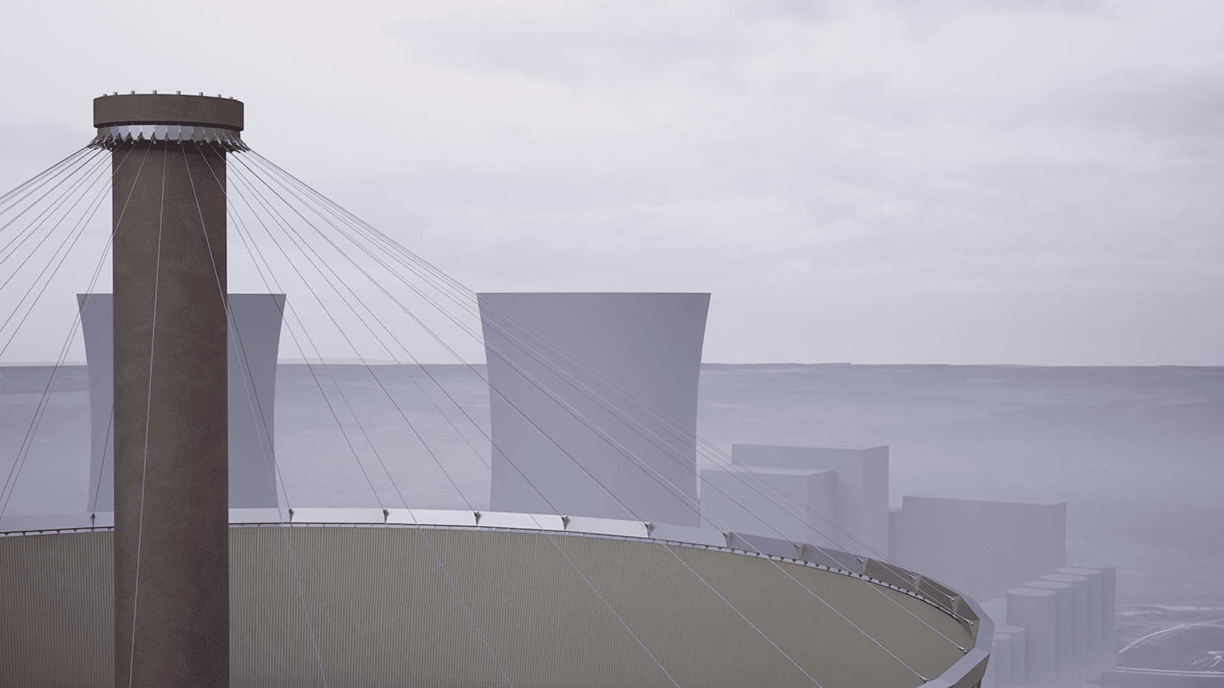
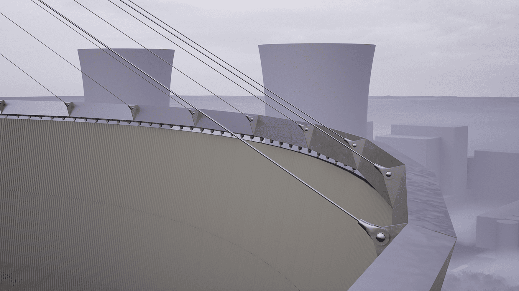
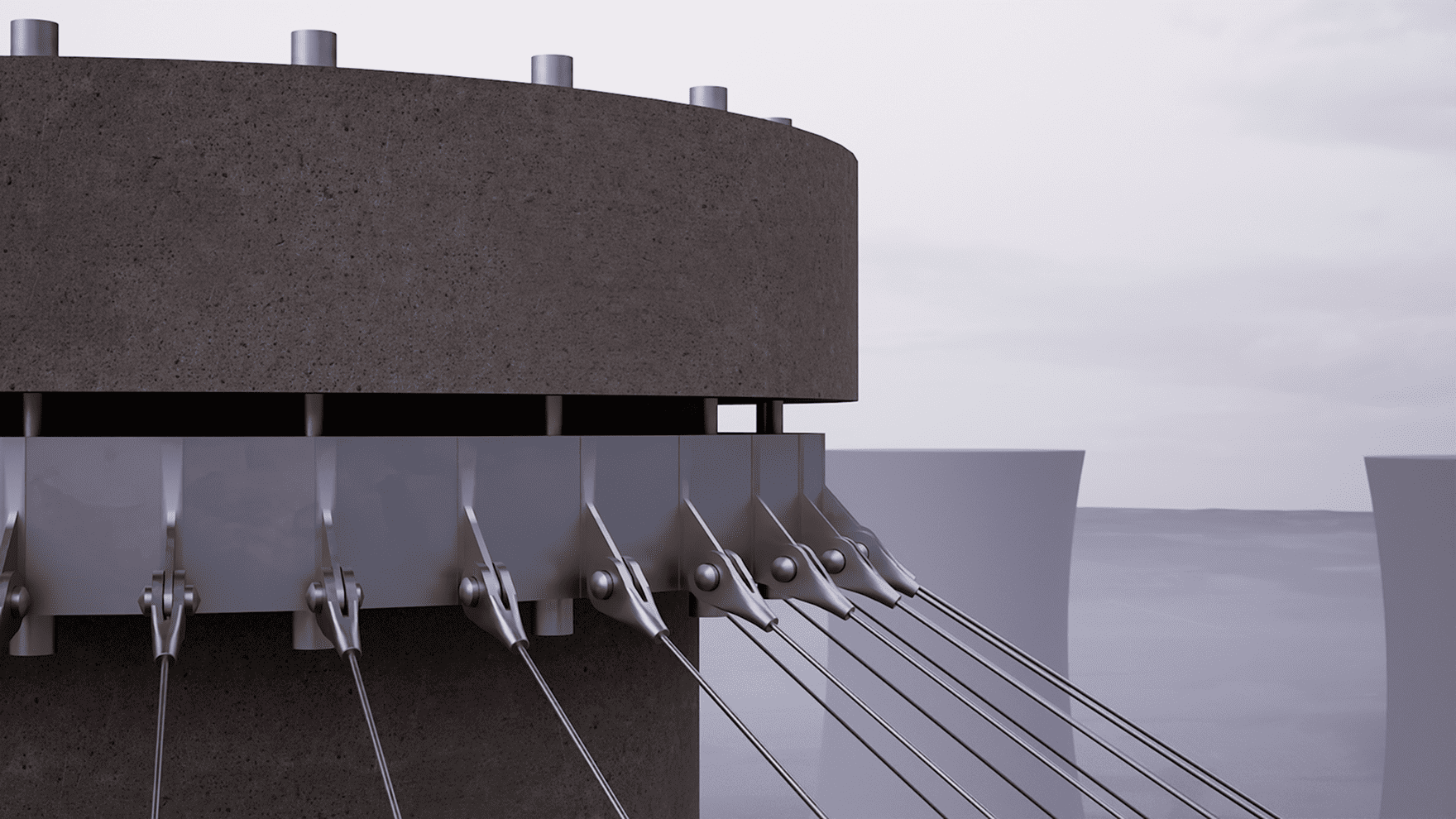
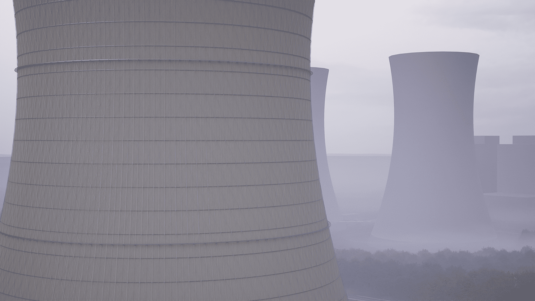
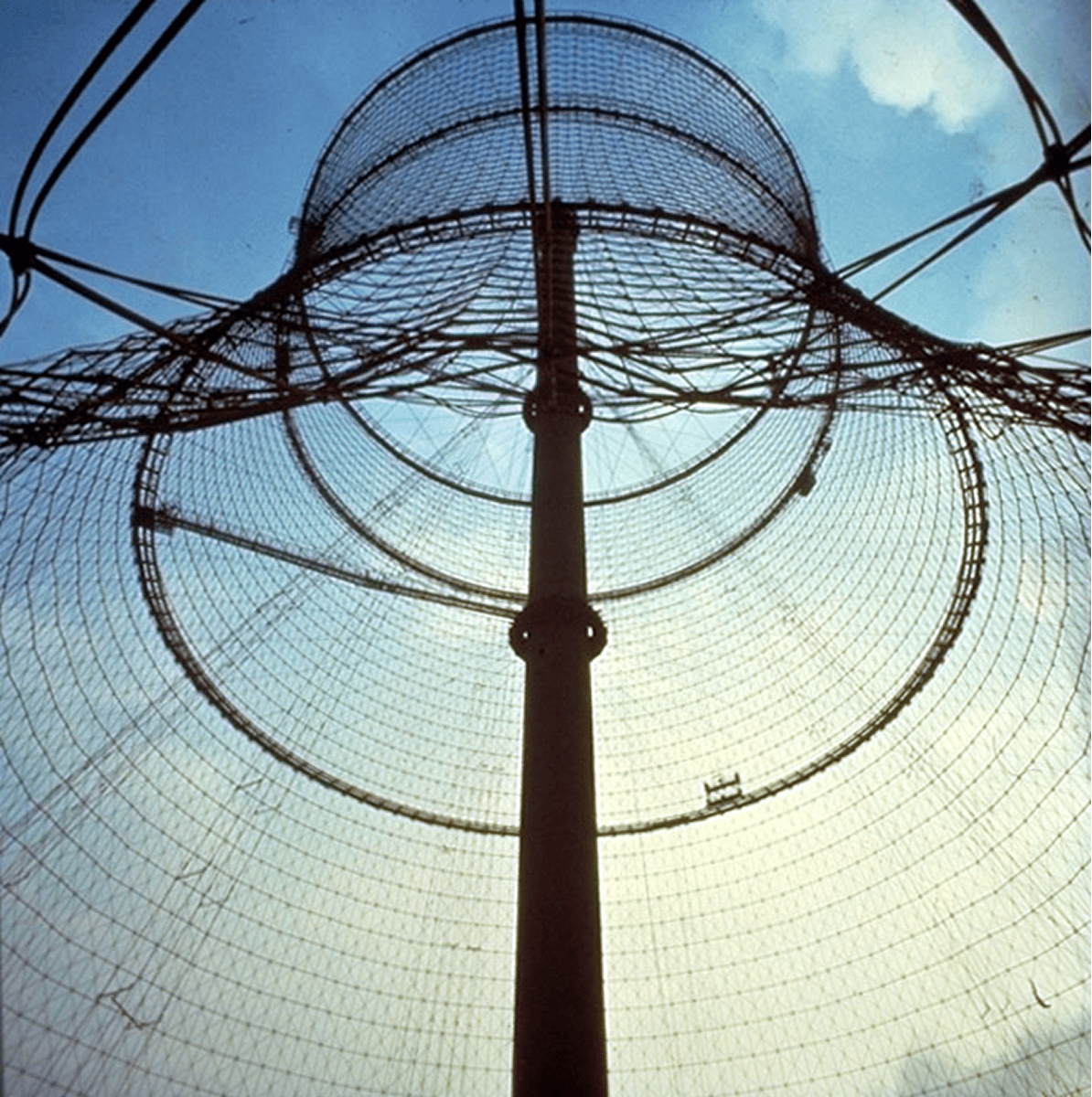
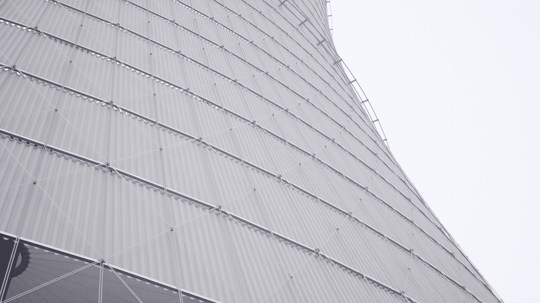
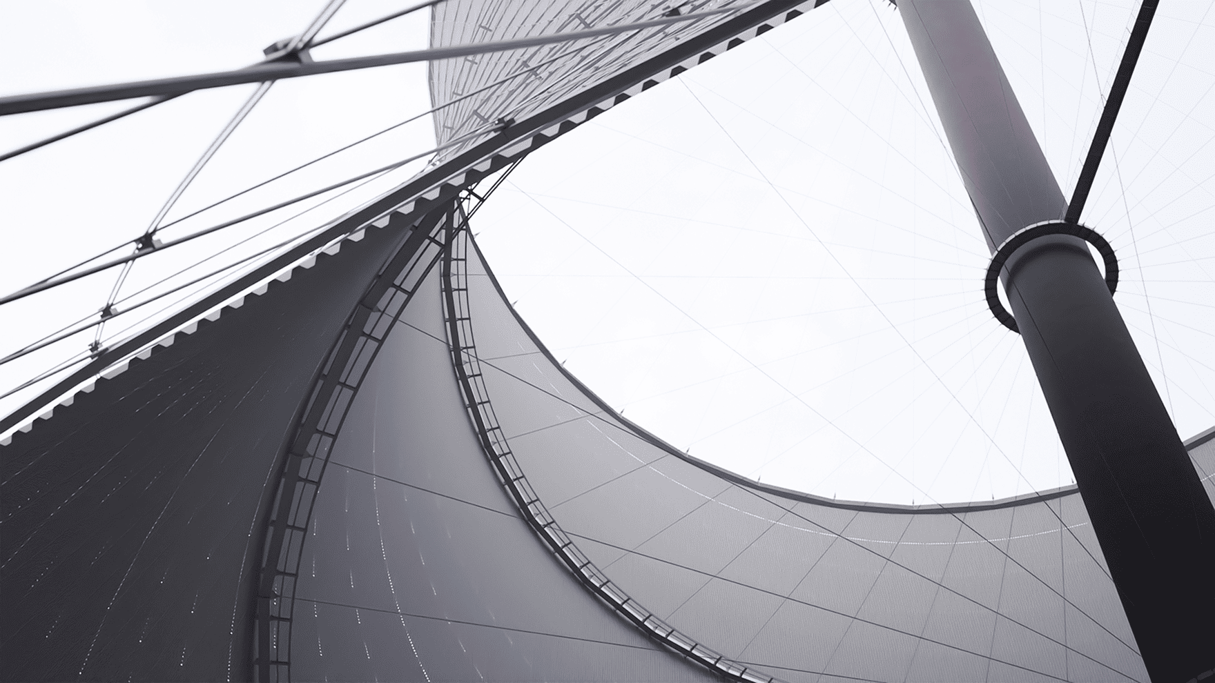
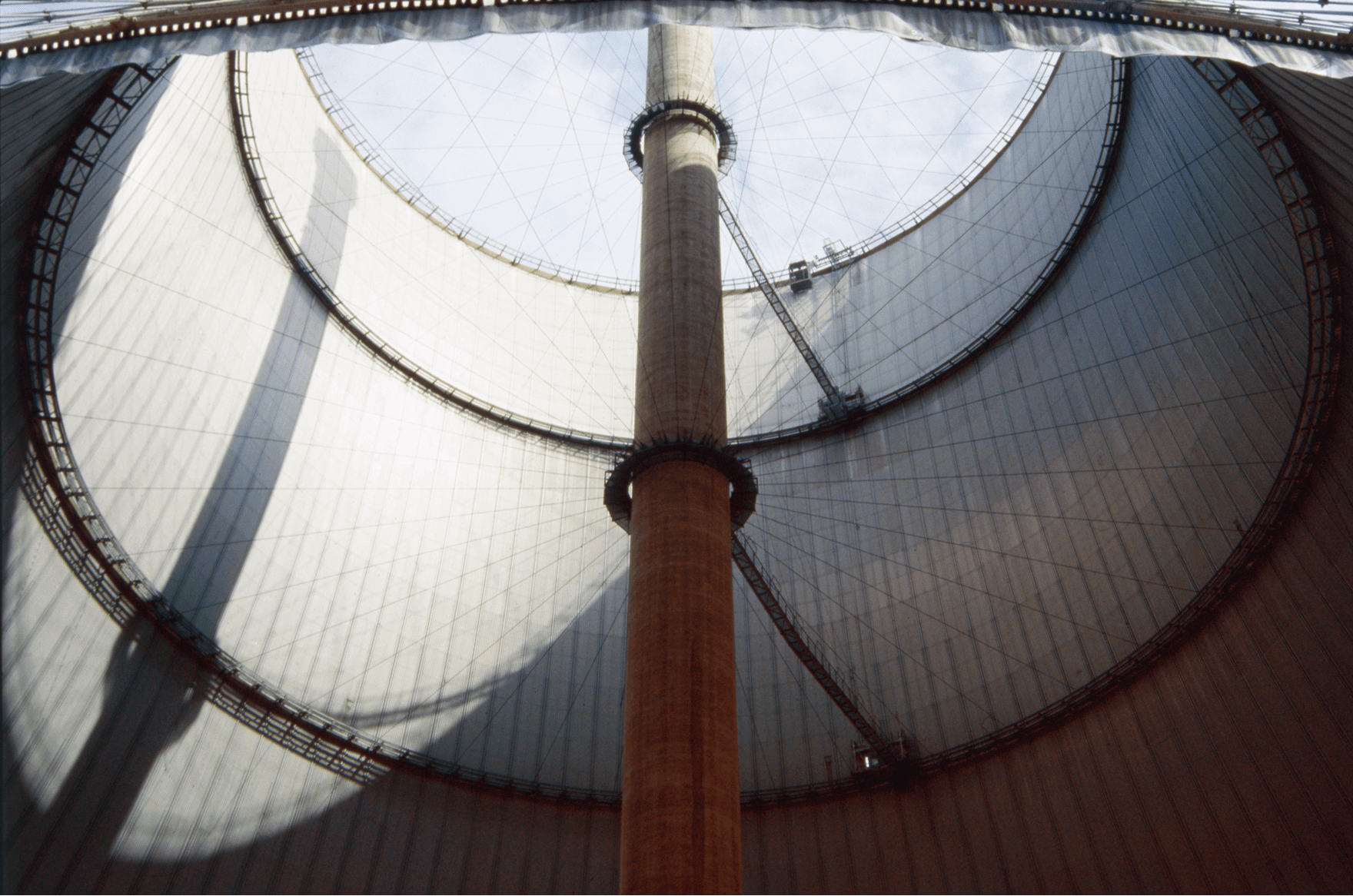
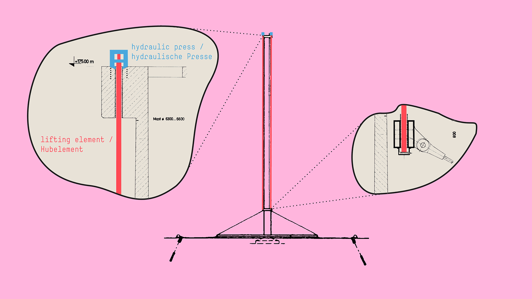
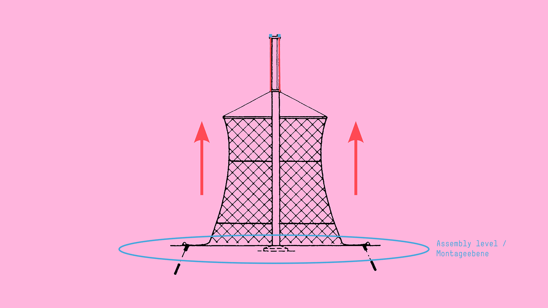
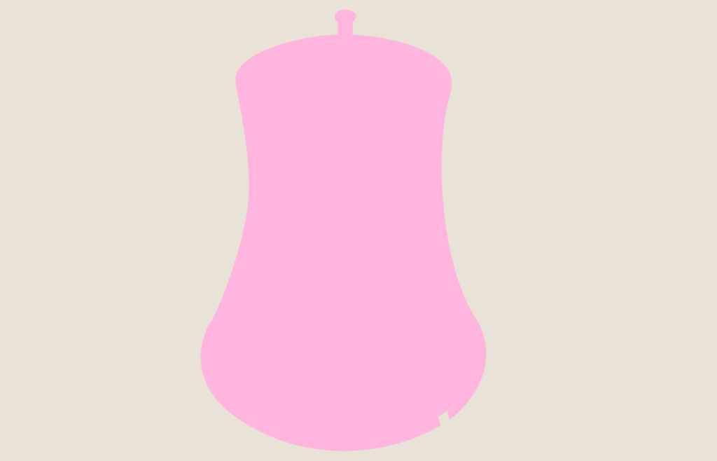
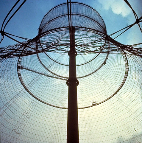
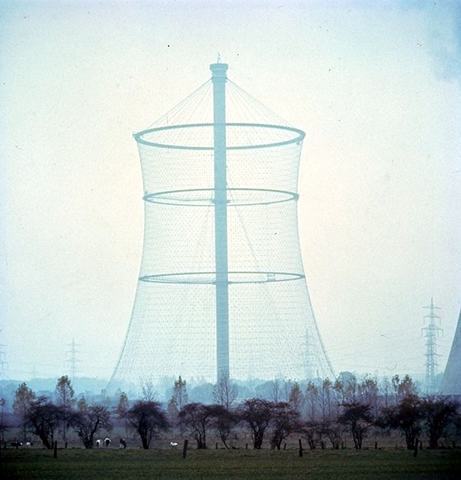
  • In particular, the shape of the cable net cooling tower—a rotational hyperboloid—is functionally justified because it supports the chimney effect and thus air cooling. Geometrically, it results from a state of equilibrium of the prestressed net structure.

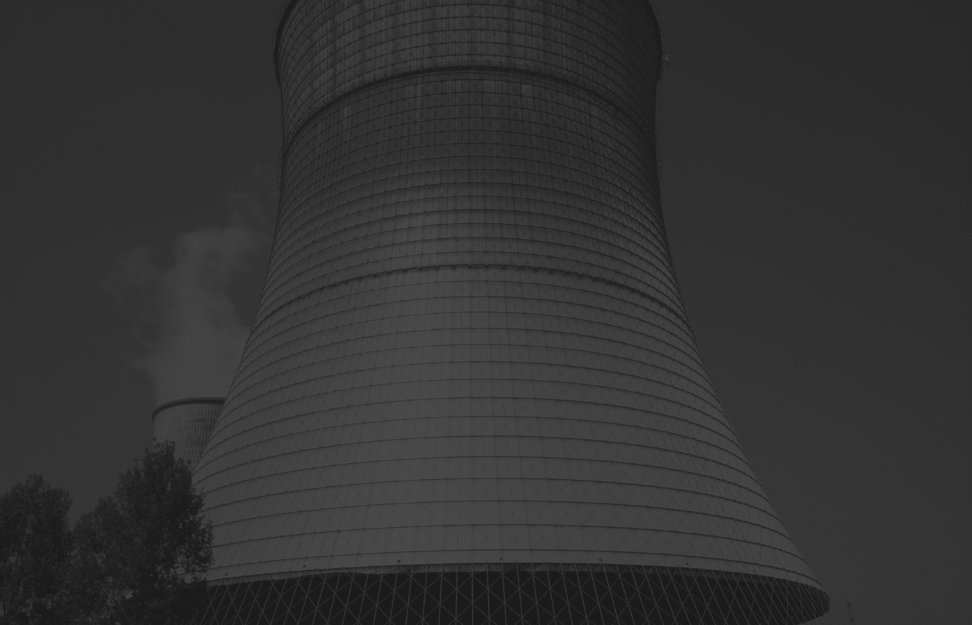
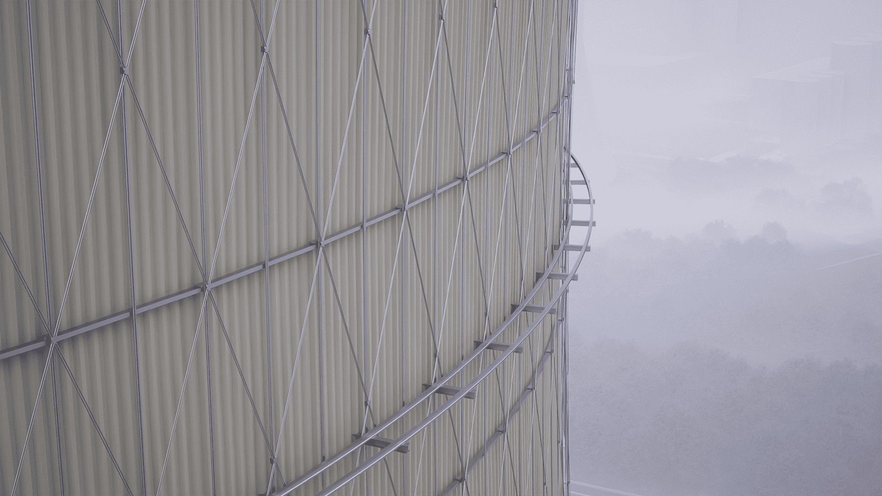
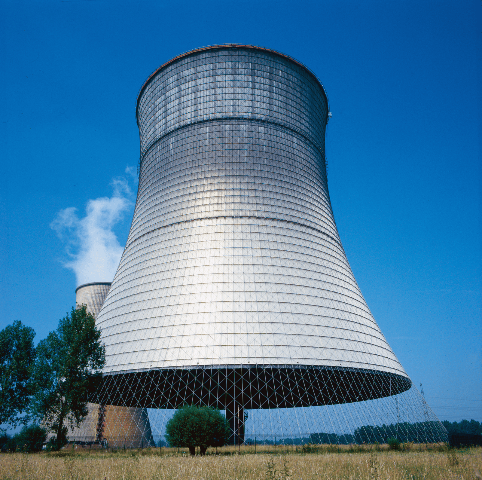
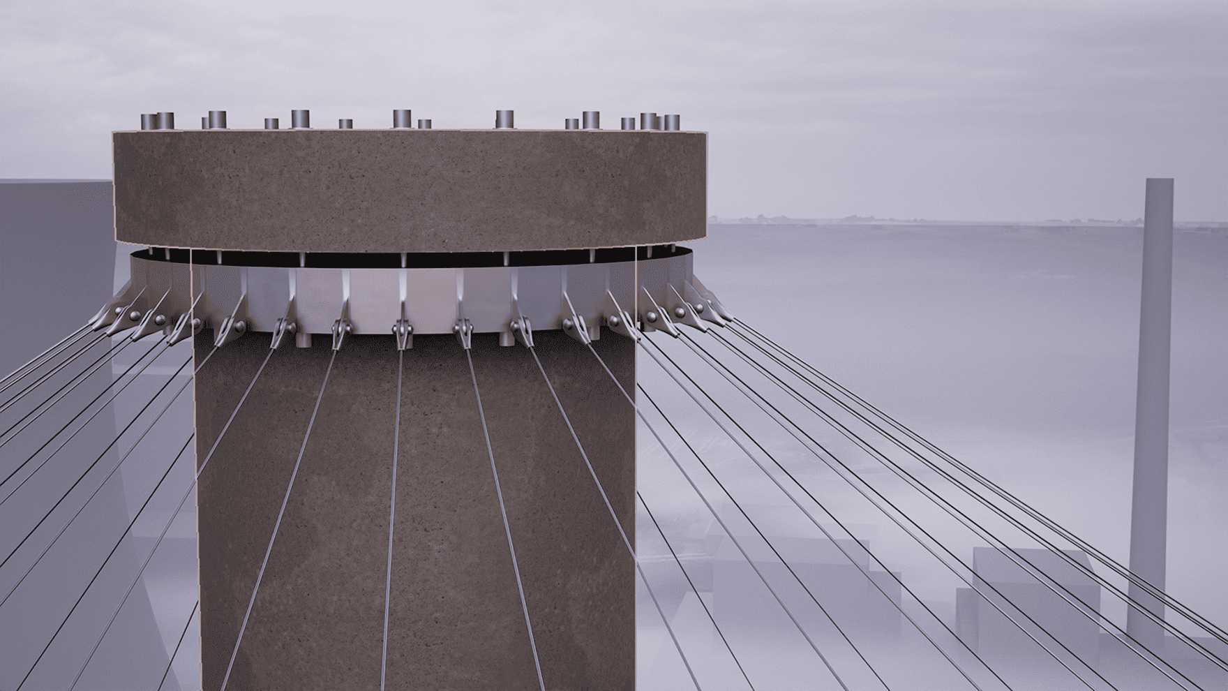
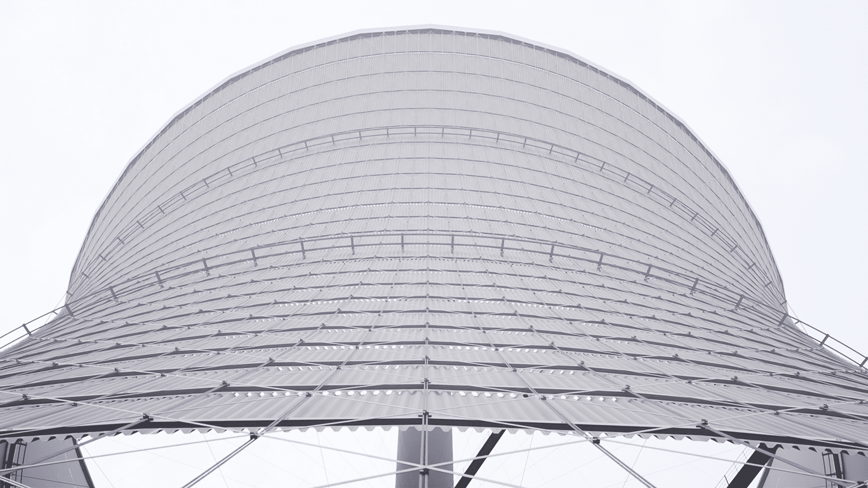
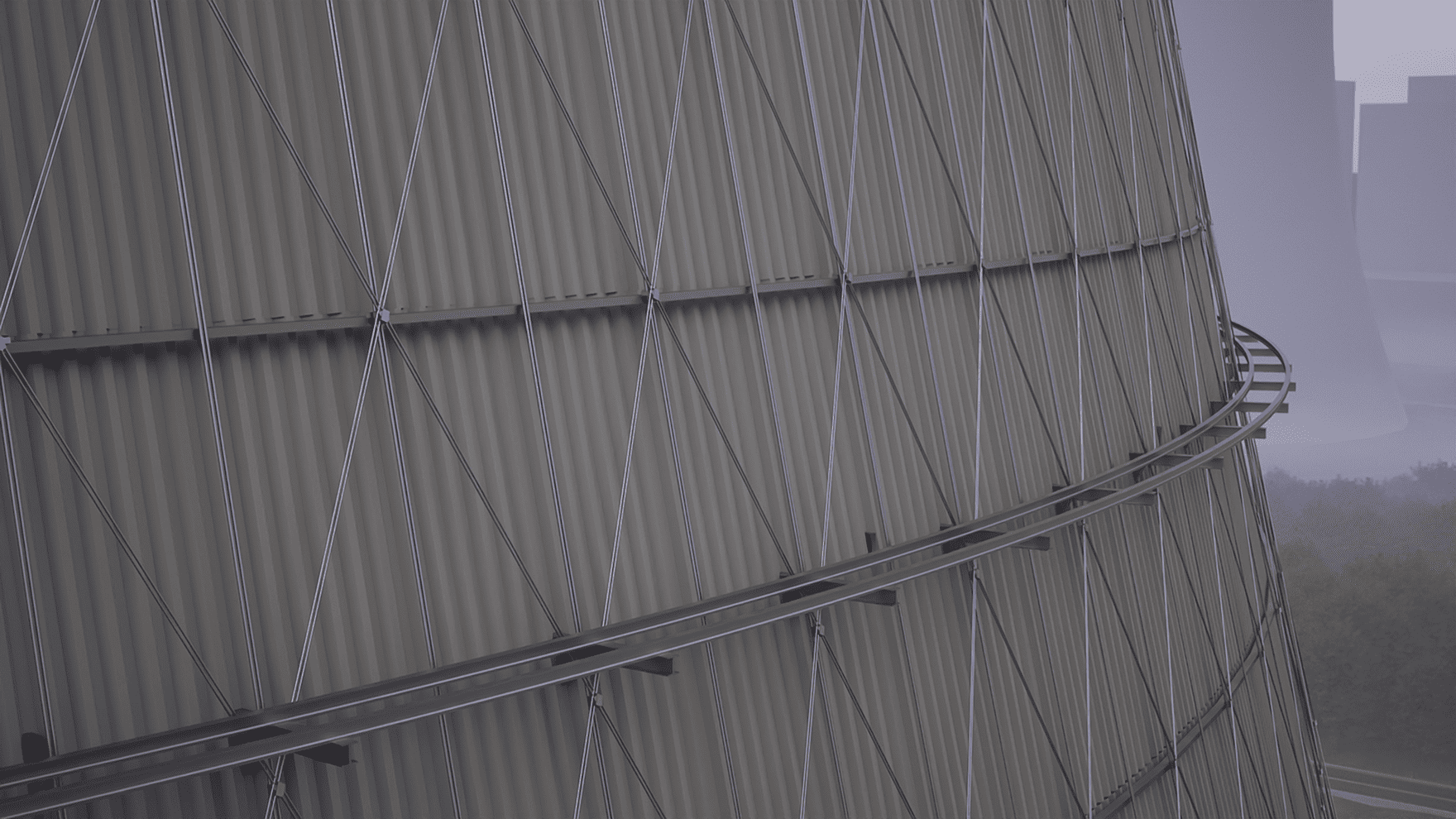
    The huge shape could easily have appeared clumsy and flat if the tower's cladding had not been placed on the inside, giving structure and definition to the external cable net.

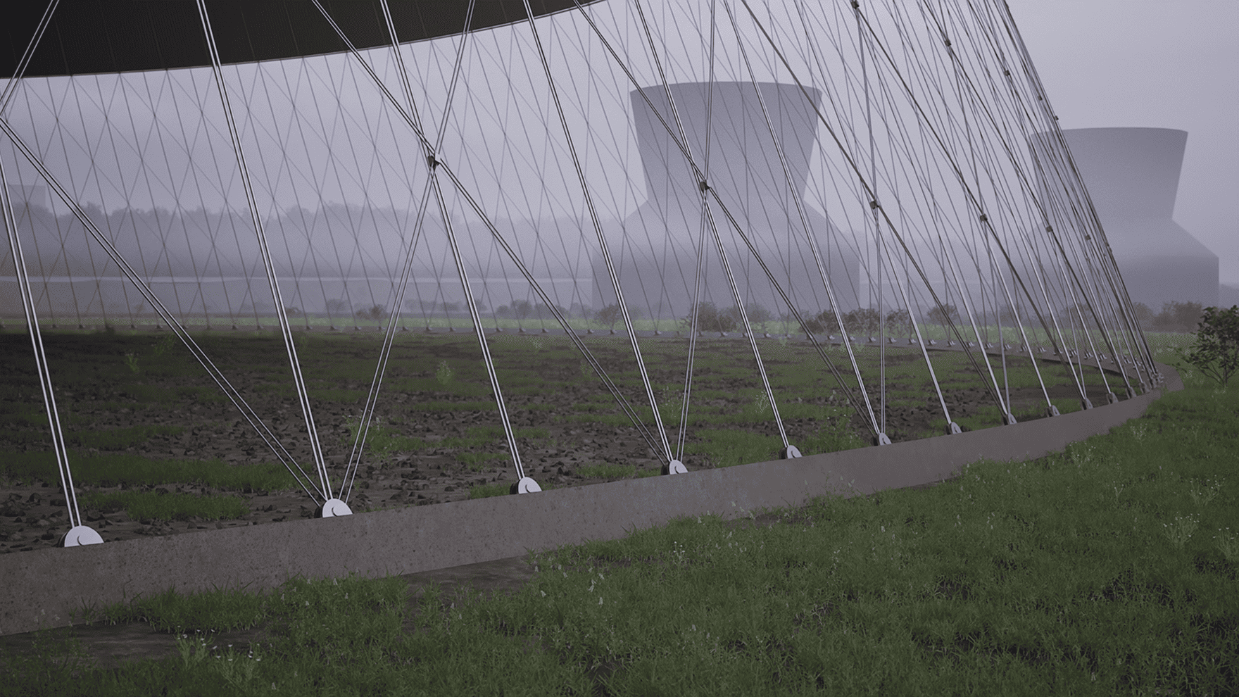
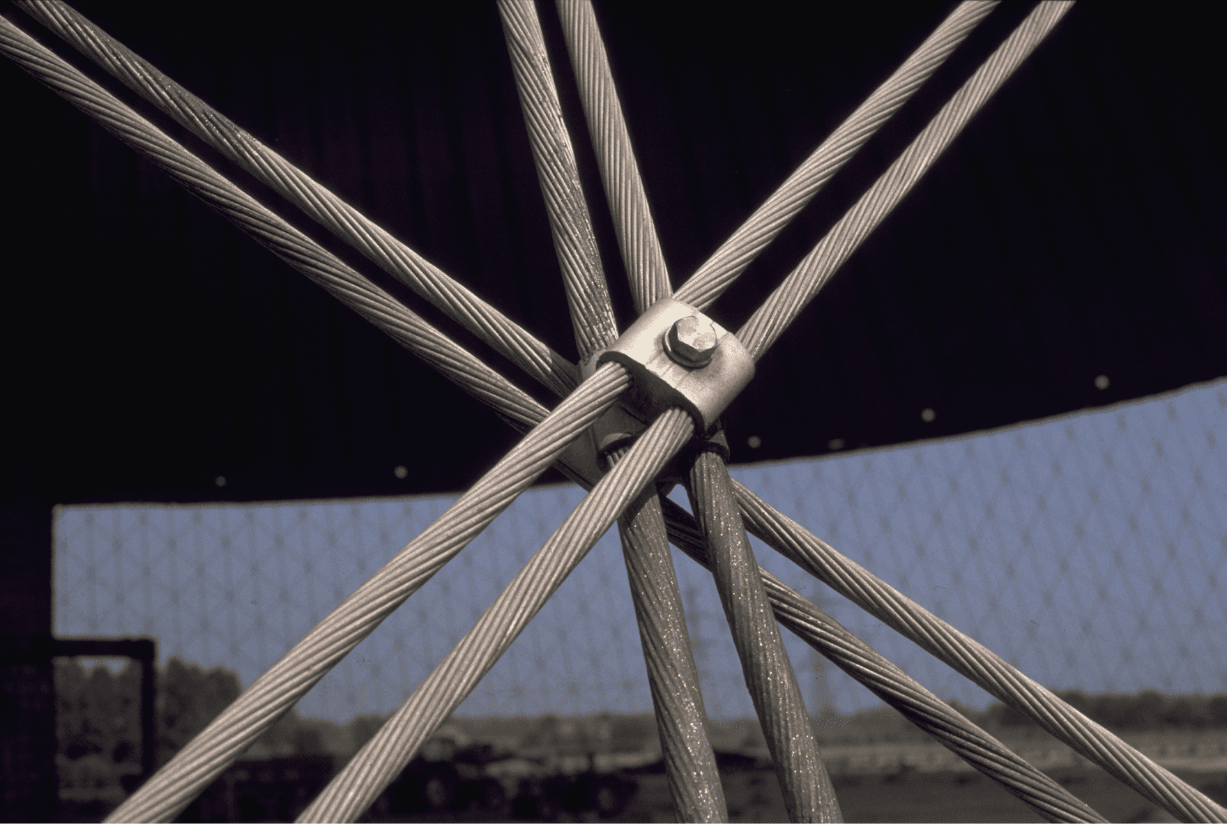
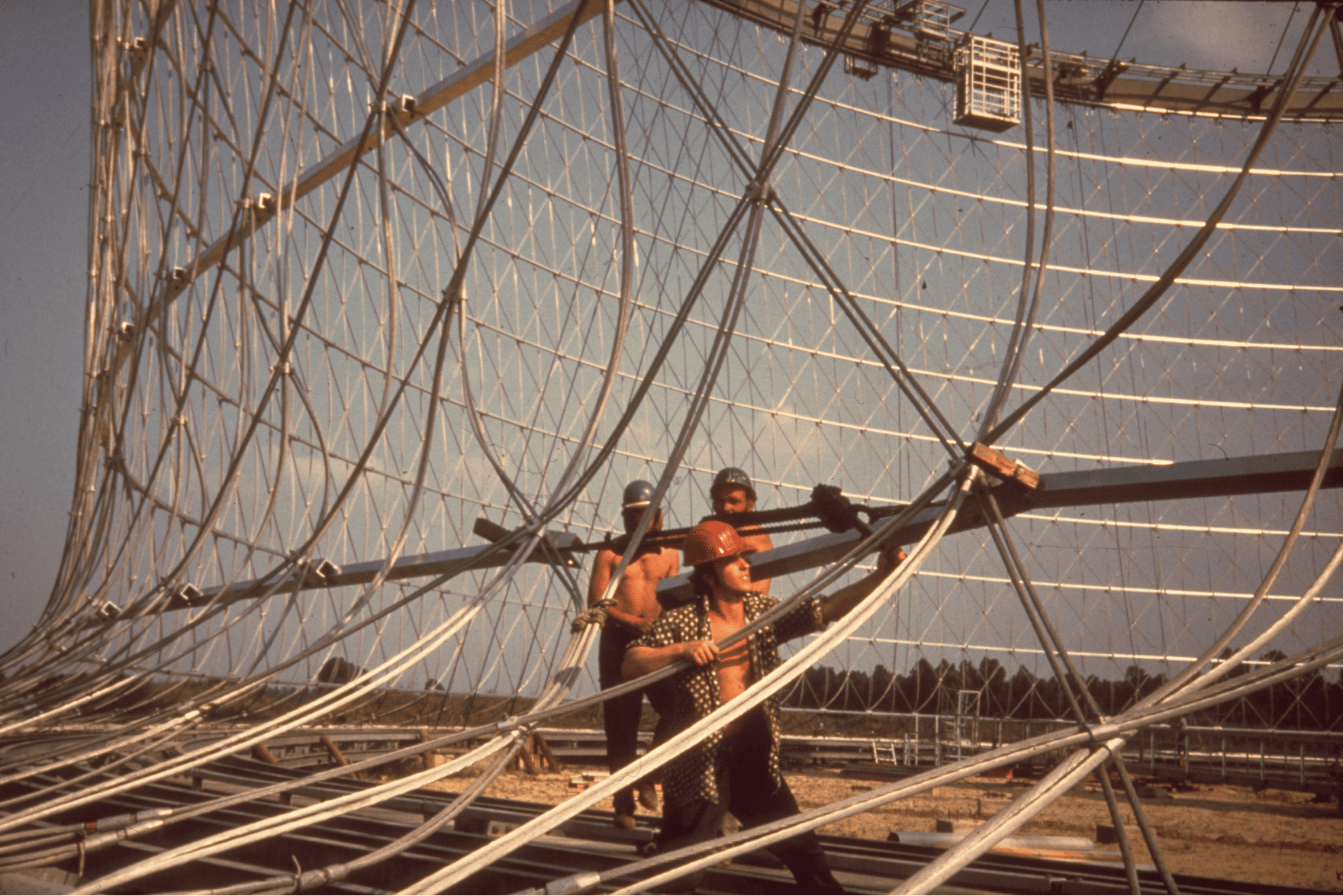
    Visibly, the cable net creates technical legibility and an “honest” design language that develops a strong presence without any design embellishments.
1-4

Dive into the structure of the cable net cooling tower

Click on the feature buttons and discover original drawings, photos, videos and explanations that tell you a story about the Art of Engineering.

The rotational hyperboloid
Basic structural layout
The dynamic behavior under wind
The ring foundation
The mast
The upper spoked wheel
The lifting ring
The two inner spoked wheels
The Cable Net
The Cladding
The construction process

The rotational hyperboloid

Basic structural layout

The dynamic behavior under wind

The ring foundation

The mast

The upper spoked wheel

The lifting ring

The two inner spoked wheels

The Cable Net

The Cladding

The construction process

The rotational hyperboloid

Basic structural layout

The dynamic behavior under wind

The ring foundation

The mast

The upper spoked wheel

The lifting ring

The two inner spoked wheels

The Cable Net

The Cladding

The construction process

The rotational hyperboloid

The cable mesh cooling tower is based on a clearly definable geometry of a double curved surface: the single-layer rotational hyperboloid; which is created by the rotation of a hyperbola. Alternatively, the double-curved surface can also be described as a surface of revolution.

The following explains how to obtain the geometry of a rotational hyperboloid.
Imagine two circles lying parallel to each other in space, one above the other at a fixed distance.
If you connect these circles with vertical lines - an infinite number of them in your mind - you first create a cylinder
If you now rotate one of the circles around the vertical axis while the other remains fixed, the cylinder twists in on itself. This twisting resembles a twisted towel - and creates the typical hyperboloid. The lines that were previously vertical are tilted but remain straight.
The stronger the twist, the flatter the straight lines, the narrower the radius in the center - the waist. The lateral surface of this body is the rotational hyperboloid.
The originally single-curved cylinder surface becomes double-curved as a result of this twisting - which brings enormous advantages for the statics: the double curvature makes the surface stiffer, more stable and efficiently dissipates forces via membrane stresses. And has therefore proven itself for the construction of cooling towers.
If the upper and lower rings were not fixed after rotation, the entire system would ‘unrotate’ again. To counteract this—or rather, to prevent rotation—straight lines in opposite directions to the original rotation must be inserted.
These principles can be used to create continuous surfaces. However, in the case of the cable net cooling tower, the structure does not consist of a continuous surface but rather individual cables, which form a prestressed membrane by fixing the lower ring and lifting the upper ring.
The underlying maths: A hyperbola is defined by the equation x² - y² = 1. If it is rotated around the z-axis, a rotational hyperboloid is created with the equation: x² + y² - z² = 1. This means that all points on the lateral surface are assigned to a function.
1/7

Basic structural layout

The cable net cooling tower consists of a central mast, a circumferential cable net shaped as a rotating hyperboloid as well as a lower foundation ring and an upper pressure ring, which is designed as an Advent wreath.

External forces - especially wind loads- are absorbed by the pre-tensioned cable net and dissipated into the ground.
The cable net consists of one set of meridional cables and two sets of diagonal cables inclined at a shallower angle than the generatrices of the paraboloid. The inclination of the diagonal cables was continuously varied along the height so that, in the most unfavorable combination of all load cases, the material utilization would be as uniform as possible.
The structural behavior of the cable net is based on an equilibrium of internal forces. The radially outward-acting deviation forces of the highly pre-tensioned meridional cables are counteracted by the inward-acting force components of the diagonal cables. This mutual force compensation creates a self-stable, pre-tensioned membrane structure that efficiently carries both its own weight and wind loads.
36 inclined cables connect the mast head to the upper compression ring. This compression ring hangs like an Advent wreath at the top of the mast and ensures that the pretension state of the cable net is maintained. At the same time, it acts as a stiff partition (bulkhead) distributing loads and deformations.
The central reinforced concrete mast serves as the vertical load-bearing axis and absorbs the entire net pretension at the mast head—it is subjected purely to compression in the final state.
If assembly conditions were not critical, the mast could be designed as a pendulum column to carry the 58 MN pretension force of the cable net.
The two horizontal spoked wheels also act like static bulkheads. They stiffen the structure in the transverse direction and prevent local deformations. Their positioning at 68 m and 112 m height ensures an even distribution of forces and makes the net very robust against wind and imperfections.
The force distribution in the cooling tower is nearly uniform throughout the entire structure due to the prestressing. The prestressing forces cause tensile forces in the cable net. In the lower section, the net transfers these tensile forces to the ring foundation, which is securely anchored in the ground by permanent anchors.
1/7

The dynamic behavior under wind

The dynamic behavior of the cable net cooling tower was analyzed using emerging numerical calculation methods at the time. The following outlines the approach taken by the involved designers.
Dynamic load bearing can result from both earthquake and wind loads. However, seismic events do not cause significant stresses in this kind of structure. This is due to the low mass of the cable net tower and its high natural frequency, making it highly resilient to dynamic loads. Consequently, additional safety measures against seismic effects were deemed unnecessary. The decisive dynamic effects were caused by wind loads.
To realistically capture the aerodynamic effects, extensive wind tunnel tests were conducted at the University of Stuttgart. Among other things, wind pressure coefficients on the exterior and interior surfaces of the tower were investigated, with particular attention given to the surface roughness caused by the cable net.
There was considerable discussion about whether the tower cladding should be applied to the outside of the net or mounted on the inside. However, the wind tunnel tests showed that a cable net situated at the outside significantly reduces the suction forces on the tower flanks, eliminating the need for additional vertical vortex generators— which are necessary for smooth surfaces.
The aim was to develop a structure with optimal structural performance and minimal material consumption using numerical methods. For this purpose, a custom calculation program was developed within eight weeks on an IBM 370/155, enabling the analysis of more than 60 tower configurations with varying geometry, cross-sections, and prestressing.
In each calculation, different load case combinations were considered, compared and thus the effects of individual load cases examined: i) self-weight only (g), ii) self-weight + prestressing (g+v), and iii) self-weight, prestressing, and wind (g+v+w).
The results show that the axial forces in the central mast are only slightly affected by wind loads. Even under full load, the deformations (partly resulting from unintended eccentricities) remain very small. Therefore, for the structural design of the mast, only assembly conditions are critical—not the operational loads.
The two horizontal spoke wheels have a highly positive effect on the deformation behavior of the covered cable net. The maximum displacement at the mast tip remains only 14 cm even under full load. At the same time, the spoke wheels distribute the membrane forces favorably along the shell.
The net was designed so that the axial forces in the shell (nz) have largely uniform magnitudes throughout the entire height. This uniform utilization of the cable net was a central criterion in selecting the geometry of the cable net.
The calculations show that the spoke wheels absorb and redistribute locally occurring shear forces, clearly demonstrating their structural function, particularly under wind loads (jumps in the force distribution).
The results refer to the final, optimized tower configuration of the calculation program. At that time, numerical methods for structural assessment were still in their infancy. Nevertheless, this project represents a remarkable example of the Art of Engineering.
1/7

The ring foundation

The ring foundation, with a diameter of 141 m, forms the base of the supporting structure. It is a ring-shaped strip foundation embedded in the ground and serves merely as a coupling element between the ground anchors and the cable net.
As a coupling element fhe ring foundation primarily requires only crack-distributing reinforcement to ensure a joint-free construction.
At the ring foundation 216 cable net cables are anchored. Each cable transmits enormous tensile forces, which are transferred into the ground through the concrete foundation.
In addition to the 216 cable anchors, 432 ground anchors are installed in the ring foundation. These are rigidly connected to the concrete and were tensioned to 1.1 times the final net prestressing force.
1/7

The mast

The mast is a 180 m tall cylindrical reinforced concrete tube with an outer diameter of 6.6 m, founded on a circular base. It forms the central load-bearing axis of the entire cooling tower and serves as the vertical suspension point for the cable net.
Structurally, the mast acts like a pendulum column in the final state, carrying the entire vertical prestressing force of the net—approximately 58 MN of compression.
The mast was constructed using slipform technology, allowing continuous casting without construction joints. It stands on its own circular foundation with a diameter of only 15.5 m—extremely efficient relative to its height.
At the top end, a head console is installed through which vertical tension members (Dywidag rods) are guided. This console serves as the anchorage point for the lifting equipment during construction.
During the construction phase, the mast was temporarily braced laterally with additional tension rods to safely carry the assembly loads.
1/7

The upper spoked wheel

The upper spoked wheel is located at a height of approximately 150 m and has a diameter of 88 m. It consists of 36 hollow box segments (80 × 120 cm) with plate thicknesses ranging from 22 to 28 mm and was made from high-strength steel (St. 52)
As a compression ring, the upper spoked wheel redirects the tensile forces of the cable net and transfers them via inclined cables to the mast head. The compression ring stiffens the cable net structure at the top.
From the outer ring, 36 cables run at an inclination of approximately 30° toward the top of the mast, where they are attached to a tension ring. These inclined cables form the link between the membrane shape and the central prestressing axis. The tension ring serves as a lifting ring during construction.
The cable net’s cables connect to the compression ring via 216 connection nodes, ensuring a secure transfer of cable forces into the compression ring.
Due to its ring-shaped, closed geometry, the compression ring is extremely stiff against deformation and distributes the forces evenly.
1/7

The lifting ring

The lifting ring raises the entire cable net with the spoked wheels step by step into its final position. In the final state, the lifting ring is attached from below to the mast head console and forms the connection between the reinforced concrete structure and the cable net structure.
The lifting ring consists of a circular hollow box section with a diameter of 7.6 m and a cross-section of approximately 60 × 80 cm. Stiffened openings in the cross-section are provided for the lifting elements and the subsequent tension members.
During the erection of the cable net, the lifting ring is connected to the mast head via lifting elements and is pulled upward in stages.
The 36 inclined cables attached to it thus continuously lift the entire net structure into its prestressed geometry.
After completion of the assembly, the lifting ring remains permanently in place and is rigidly connected to the mast by prestressed Dywidag tension members. The opening seen here was grouted with high-strength mortar.
1/7

The two inner
spoked wheels

The two spoked wheels are ring-shaped structures inserted between the mast and the cable net at heights of 68 m and 112 m. They act as load-distributing, stiffening bulkheads. Their function is to stabilize the net in the plane and secure it against deformations (e.g., due to wind).
Each spoked wheel consists of an outer and an inner ring connected by 36 radial spiral cables (Ø 35 mm). The spiral cables serve as the 'spokes'—they prestress the two rings and form a stiff spoked wheel together with them.
The outer ring is made of a steel hollow box section with cross-sectional dimensions of 50 × 40 cm and plate thicknesses of 12 – 14 mm. It acts as the compression ring of the spoked wheel.
The inner ring consists of a horizontal I-profile with dimensions of approximately 86 × 40 cm. It acts as the tension ring of the spoked wheel.
The inner rings of the spoke wheels do not touch the mast. As a result, the spoke wheels “float” and contribute solely to the bracing of the cable structure.
1/7

The Cable Net

The cable net forms the primary load-bearing structure of the cooling tower—a doubly curved membrane shell that carries only tensile forces.
The triangular cable net consists of 216 meridian cables and two diagonal cable sets with 108 cables each, whose inclination varies along the height. The cables differ in construction and dimensions.
The mesh sizes range from 2.05 m to 1.20 m due to the double curved form but remain fundamentally consistent in shape due to the triangular mesh pattern.
The meridional cable set consists of 216 vertical cables running continuously from the ring foundation up to the upper compression ring. Their task is to carry the main prestressing force in the vertical direction. Through its hyperbolic curvature, the tower takes on its characteristic tapering.
The two diagonal cable sets each consist of 108 cables. Unlike the meridional cables, they are not continuous but are spliced at the spoked wheels.
The inclination of the diagonal cables was adjusted over the height so that a uniform material utilization is achieved under all load cases.
The force equilibrium between the outward-directed deflection forces of the meridional cables and the inward-directed components of the diagonal cables was carefully maintained.
All cables consist of aluminum-coated strands with a high-strength steel core. Each cable is composed of two round strands running parallel at close distance. At crossing points, the cables are force-locked together with pressed aluminum clamps. Their diameters range between 20 and 25 mm.
The prestressing force of approximately 58 MN is distributed over all net cables. It provides the necessary stiffness and ensures that the net is already under tension in the unloaded state without external loads.
1/7

The Cladding

The cladding is located on the inside of the cable net, where the wind forces are significantly reduced by the cable structure in front of it, and at the same time serves to guide the airflow during the cooling tower’s operation.

Its main task is to channel the air inside and thereby optimize the aerodynamic function of the natural draft cooling tower.
The cladding consists of two main components:

Horizontal aluminum ring girders attached at the cable net intersections—these are horizontally movable to accommodate expansions and temperature changes.

Aluminum trapezoidal sheets stretched in the meridional direction, resting on the ring girders and forming the actual cladding surface.
The cladding is connected to the cable net via elongated holes integrated into the attachment points. This design allows thermal movements of the aluminum parts relative to the net without impairing the load-bearing structure or causing restraint forces
The total area of the cable net is approximately 46,000 m². The cladding covers only about 38,000 m² of this area. Up to a height of 19 m above ground, the net remains unclad to allow air intake.
1/7

The construction process

The construction phase of this project involved a complex sequence of steps, combining reinforced concrete structures, lifting technology, and a precisely prefabricated cable net. From the foundation and erection of the mast to the final assembly, each stage was carefully planned – the following sections illustrate this process
First, the ring foundation was poured, which later absorbs the tensile forces from the cable net. Simultaneously, the central mast was continuously constructed to its full height using slipform technology.
Next, the assembly of the upper compression ring took place at ground level: All associated steel components—compression ring, inclined cables, and lifting ring—were assembled in a circular arrangement around the mast into a single unit.
Hydraulic presses were installed at the mast head. Through vertical openings in the mast head console, lifting elements were connected to the lifting ring. Using this system, the entire upper compression ring - already partially connected to the first network cables - was lifted evenly upwards.
During the lifting process, the cable net, securely connected to the compression ring, was assembled piece by piece on the ground. At the same time, the spoke wheels and other components such as walkways and assembly platforms were lifted along with the net. The cables were prefabricated to exact measurements - on site, they only needed to be bolted together, without any re-measuring or cutting.
The lifting speed was precisely coordinated so that the feeding and assembly of the cable and steel components on the ground proceeded synchronously with the lifting. During this phase, the still un-tensioned net was temporarily stabilized only by the spoke wheels. Their inner rings were only temporarily coupled to the guyed mast to transfer loads and dissipate wind forces.
After the target height was reached, the lifting system was converted into a tensioning system. The lifting elements were replaced by tensioning elements, additional hydraulic cylinders were installed, and the net was brought into its final state by controlled tensioning. The membrane shape was now fully stable and prestressed. Finally, the joint between the mast and the lifting ring, was permanently grouted with high-strength mortar.
After tensioning, the cladding was installed using movable assembly platforms that ran on circular rails mounted on the spoke wheels. Vertically, the platforms were guided by tensioned cables, allowing them to precisely follow the shape of the tower. The aluminum cladding was then attached, with the lower section deliberately left open to allow air intake.
1/7

Explore the structure of the Cable Net Cooling Tower in the comfort of your home.

Here you can download the entire VR exhibition of the Cable Net Cooling Tower for free.

Pause

WHO MADE THIS PROJECT POSSIBLE?
WE GRATEFULLY THANK

Funding

Click here to access the complete image credits.

Where were the lost structures located? Find them on the map.

Berlin

The “Ahornblatt” Restaurant

This double-curved concrete shell structure enables large spans with minimal material use. Its futuristic form shapes the Berlin cityscape beyond the GDR era.

Berlin

The Berlin “Bauakademie”

This masonry skeleton construction is a prototype building with a uniform column grid, consisting of rib-reinforced vaulted ceilings, masonry columns , and arches, which set standards for economical and functional construction throughout Prussia.

Berlin

The “Anhalter” Train Station

This masonry structure with pin-jointed iron truss arches connects Berlin to the world. A train station whose innovative roof structure, at the time, featured the largest span in Europe.

Berlin

The Old “Kaisersteg”

This iron truss bridge with an arch and central hinge connects two districts of Berlin. With a main span of 86 meters, it was a technical masterpiece of its time and represents innovative bridge engineering of the late 19th century.

Schmehausen

The Cable Net Cooling Tower

The cable-net cooling tower of the Hamm-Uentrop nuclear power plant in Schmehausen is globally unique in its design. The load-bearing network of steel cables replaces traditional concrete structures, enabling an exceptionally lightweight and efficient construction.

Munich

The Munich Glass Palace

This cast steel and glass structure is built in 1854 using innovative industrial manufacturing processes in a very short time. Although intended as a temporary building, it shaped Munich’s reputation as a city of art for over 75 years through its exhibitions.

Weimar

The Hetzer Timber Halls

The timber halls of the company Otto Hetzer AG were based on a construction principle patented in 1906: glued and curved timber elements that enabled large spans – a groundbreaking innovation in timber construction.

Awareness information

Seilnetzkühlturm:

A structure like the Cable net cooling tower deserves recognition for its technical distinctiveness. Even today – preserved in digital form – it bears witness to engineering elegance and pioneering spirit. At the same time, it stands as a symbol of an era of energy production: nuclear power. A technology that, in 21st-century Germany, is no longer considered socially or politically sustainable.

The tower for dry cooling of process water from industrial operations – in this case, nuclear power generation – was conceived as an alternative to conventional concrete cooling towers. However, it remained an elegant prototype: construction was partially completed in 1983, handed over to the operator at the end of 1987, and operated until early 1989. Only two years later, the tower was demolished.
This unique structure opens a discourse — on technical visions, political decisions, and the question of what kind of future we want to help build.

An interesting insight into this topic, including quotes from Jörg Schlaich, can be found in a taz article from 1991, written before the tower’s demolition had taken place.

Let’s talk

Collaborate
with us

You have ideas for the content development of the museum and would like to exchange thoughts with us? We’d love to hear from you!

Collaborate as a Museum

Your museum is interested in a partnership? We offer a curated exhibition that we’d be happy to bring to your institution. Get in touch – we look forward to working together!

Become
a Partner

You’re passionate about structural engineering and believe in the importance of sharing it with others? We have big plans and are looking for committed partners. We’d love to hear from you!